Power insulating part leakage current monitoring equipment
A technology for monitoring equipment and leakage current, which is applied in the direction of only measuring current, measuring current/voltage, measuring electricity, etc., can solve the problem of relying on manual inspection of insulating parts, and achieve the effect of easy judgment
- Summary
- Abstract
- Description
- Claims
- Application Information
AI Technical Summary
Problems solved by technology
Method used
Image

Examples
Embodiment 1
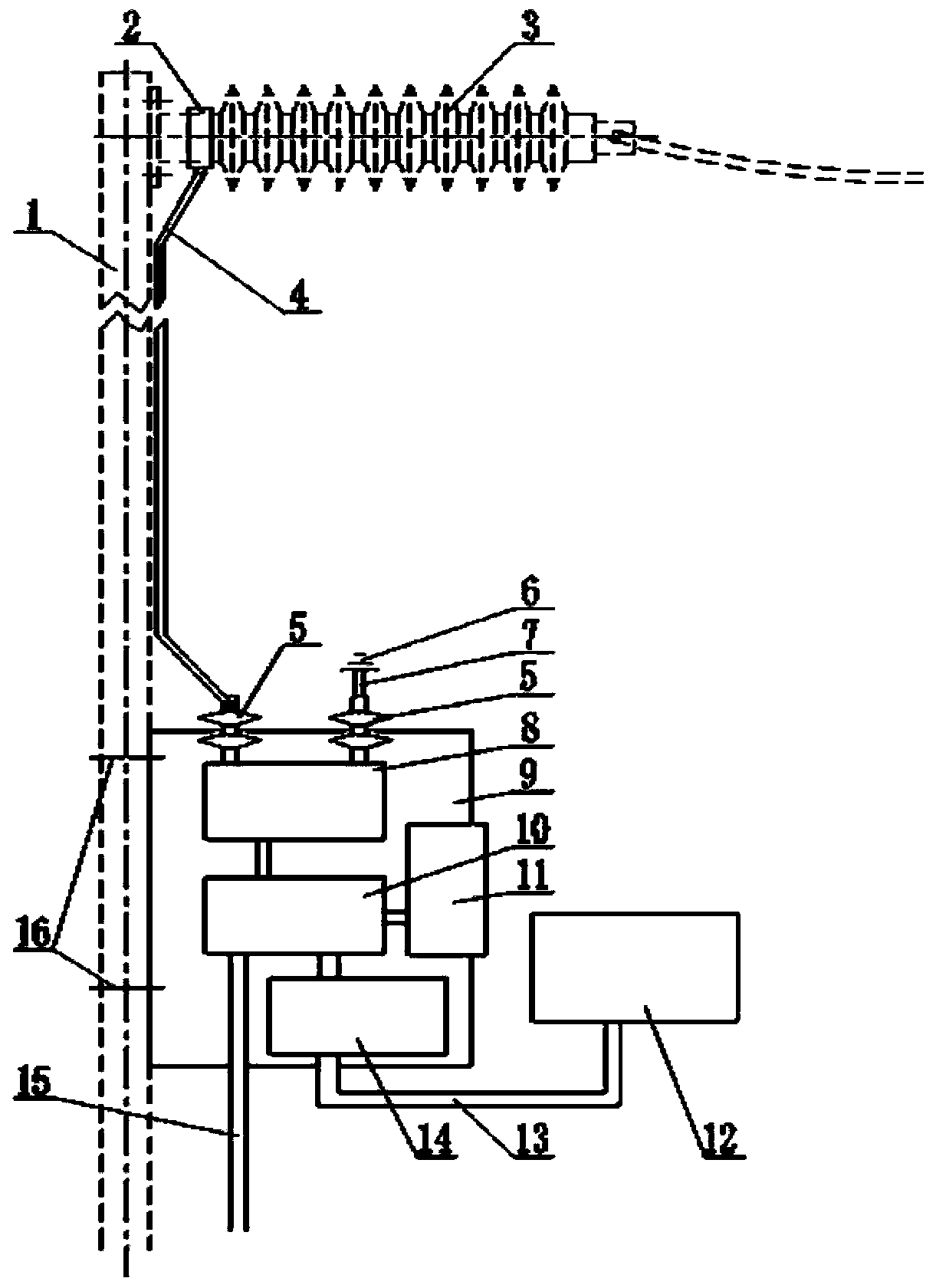
[0028] Such as figure 1 As shown, it is the voltage form of one side of the insulator installation, that is, the one-side voltage insulator 3 is the existing electrical equipment under test, the one-side voltage insulator 3 is set on the side of the pillar 1, and the buckle-type electrical connector 2 is fastened and installed on one side The insulated end of the voltage insulator 3 is connected to the metal conductor 5 with external solid insulation of the monitoring equipment 9 through a high-insulation low-resistance electric wire 4, and the other metal conductor 5 with external solid insulation is connected to the earth 6 through a grounding wire 7 The other ends of the two metal conductors 5 with external solid insulation are connected to the precision current collection device 8, and the calculation current is collected in the precision current collection device 8, and the temperature, humidity and environment collector 11 collects on-site weather data. The unit 10 corre...
Embodiment 2
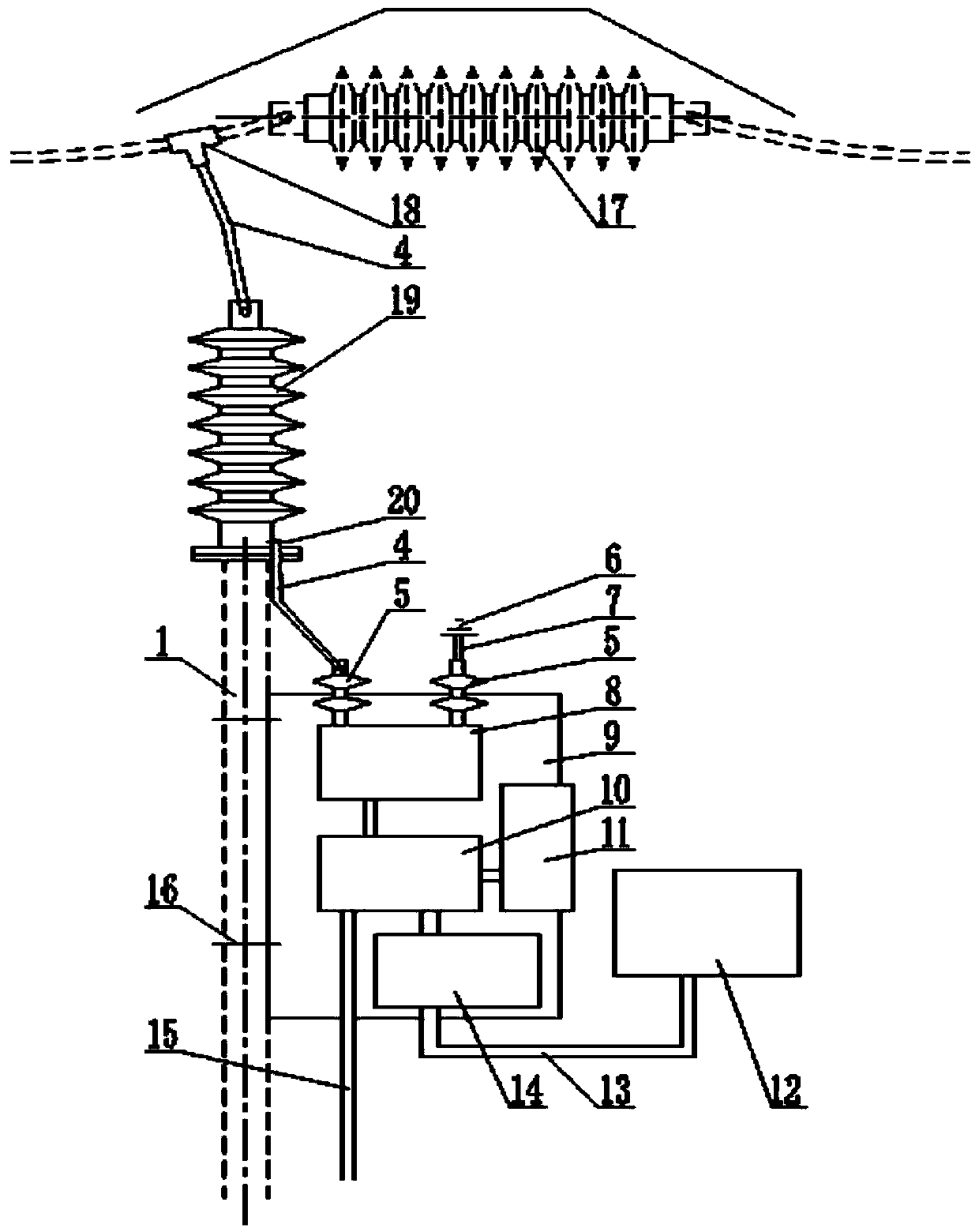
[0030] Such as figure 2 As shown, it is the double-sided voltage form of the insulator installation, that is, the double-sided voltage insulator 17 is the existing electrical equipment under test, and the metal clamp 18 connects the high-insulation and low-resistance electric wire 4 to one side of the double-sided voltage insulator 17, and the high insulation and low resistance The other side of the electric wire 4 is connected with the zinc oxide type gapless connection device 19, and the spool electrical connector 20 connects one end of the high insulation and low resistance electric wire 4 with the zinc oxide type gapless connection device 19 spool leading end, and the other end The metal conductor 5 with external solid insulation connected to the monitoring equipment 9, the other metal conductor 5 with external solid insulation is connected to the earth 6 through the ground wire 7, the other ends of the two metal conductors 5 with external solid insulation Connected to th...
Embodiment 3
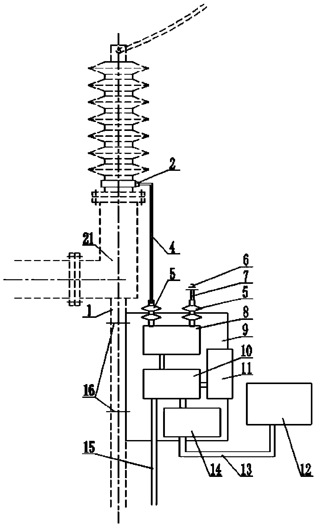
[0032] Such as image 3 As shown, when the monitoring device 9 is used on electrical equipment, its form can also be installed as image 3 , the high-voltage switchgear 21 in the dotted line is the existing electrical equipment under test. The high-voltage switchgear 21 is set on the pillar 1, and the buckle-type electrical connector 2 is fastened to the end of the insulator of the high-voltage switchgear 21. Through high insulation and low resistance The electric wire 4 is connected to the metal conductor 5 with external solid insulation of the monitoring equipment 9, and the other metal conductor 5 with external solid insulation is connected to the earth 6 through the grounding wire 7, and the two metal conductors 5 with external solid insulation The other end is connected to the precision current collection device 8, and the calculation current is collected in the precision current collection device 8, and the temperature, humidity and environment collector 11 collects on-s...
PUM
 Abstract
Description
Claims
Application Information
 - R&D Engineer
- R&D Manager
- IP Professional
- Industry Leading Data Capabilities
- Powerful AI technology
- Patent DNA Extraction
Browse by: Latest US Patents, China's latest patents, Technical Efficacy Thesaurus, Application Domain, Technology Topic.
© 2024 PatSnap. All rights reserved.Legal|Privacy policy|Modern Slavery Act Transparency Statement|Sitemap