NMR-Magic Angle Rotary Probe with Oscillable Stator

A technology of nuclear magnetic resonance and swing angle, which is applied in the direction of magnetic resonance measurement, measurement of magnetic variables, instruments, etc., and can solve problems such as damage

A technology of nuclear magnetic resonance and swing angle, which is applied in the direction of magnetic resonance measurement, measurement of magnetic variables, instruments, etc., and can solve problems such as damage

CN110133550BActive Publication Date: 2020-10-16BRUKER BIOSPIN

Image

  • NMR-Magic Angle Rotary Probe with Oscillable Stator
  • NMR-Magic Angle Rotary Probe with Oscillable Stator
  • NMR-Magic Angle Rotary Probe with Oscillable Stator

Examples


Embodiment Construction

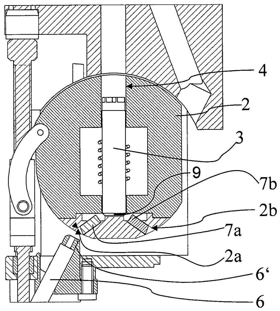
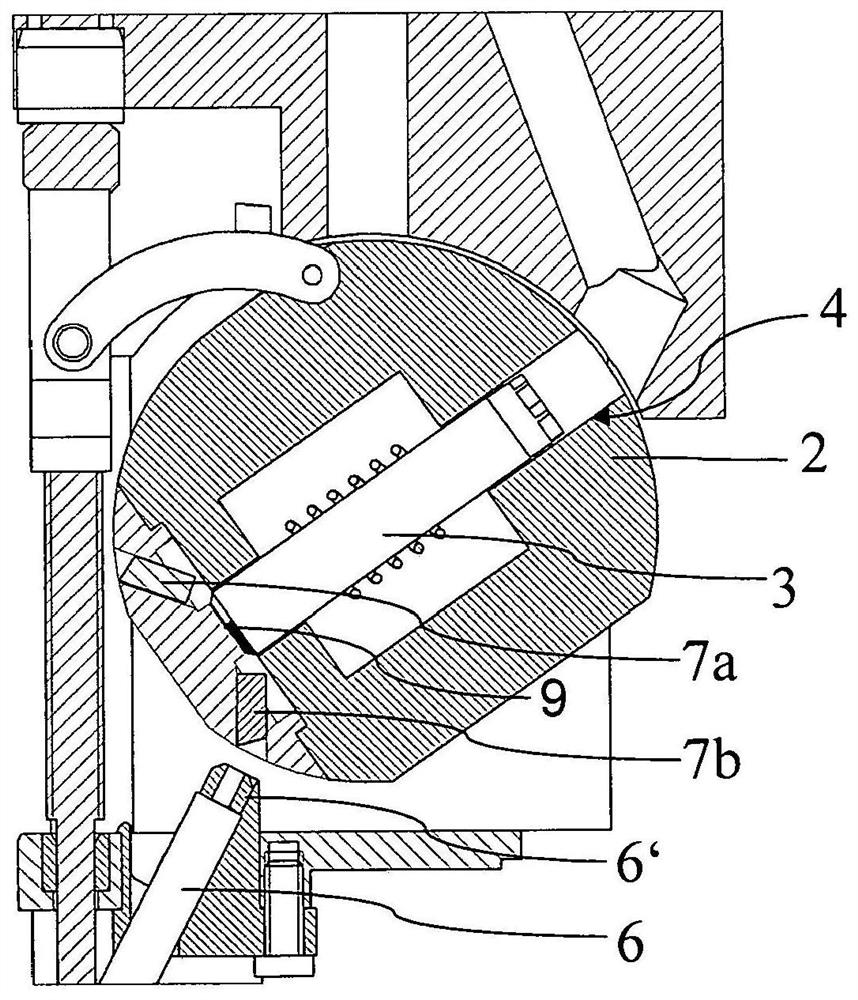
[0055] The invention relates to a specially modified probe head for NMR-MAS spectrometers, in which no mechanical shifts and additional moving components are required for contactless and reliable detection of the current configuration of the swivelable MAS stator, that is to say for the MAS rotor in the MAS Presence detection in the stator. Such NMR-MAS spectrometers usually have a temperature-adjustable probe in the NMR measuring device, which includes the NMR magnetic system, the shim system, the turbine and the transport of the MAS rotor with the measurement sample from outside the NMR magnetic system up to A device for measuring the position of the MAS rotor in an NMR probe.

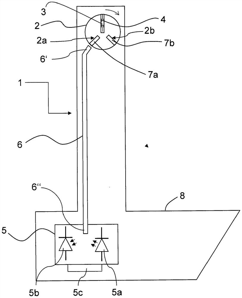
[0056] figure 1 The NMR-MAS probe 1 according to the invention is shown in vertical section. Such as figure 1 As shown, the probe 1 according to the invention comprises a MAS stator 2 for accommodating a MAS rotor 3 which can be set in rotation in a measuring position in which the column axis of t...


PUM


Abstract

A probe head (1) of an NMR-MAS assembly has a stator (2) with an opening (4) receiving a rotor (3) which, in a measuring position, rotates at the magic angle to the B0 field. The stator is pivotable between the measuring position and a loading position of the rotor. A detection device (5) permits external, contactless identification of whether the opening of the stator is fitted with a rotor. The detection device has a light source (5a), from which light is introduced into a lower end (6″) of a light guide (6). The stator has a first bore (2a), in which a first light guide stump (7a) is positioned such that, in the loading position of the stator, it produces an optical connection between a rotor inserted in the stator and an upper end (6′) of the light guide opposite the lower end.

Description

technical field [0001] The invention relates to a probe of a nuclear magnetic resonance (NMR)-magic-angle-spin (MAS) device with a magic-angle-rotating stator for accommodating a magic-angle-rotating rotor capable of being placed in a measuring position In rotation, the column axis of the magic-angle rotating rotor in the measuring position is aligned with the B of the NMR-magic-angle rotating device 0 The field becomes a magic angle, wherein the magic-angle rotating stator has an opening for introducing the magic-angle rotating rotor, wherein the magic-angle rotating stator is set in such a way in the nuclear magnetic resonance-magic-angle rotating probe that the magic-angle rotating stator can be Pivoting between the measuring position and the loading position, in which the magic-angle rotating rotor can be introduced into the magic-angle rotating stator. Background technique [0002] Such an NMR-MAS probe is known from DE 10 2013 201 110 B3 (=ref. [1]). [0003] Documen...

Claims


Application Information

Patent Timeline
16 Oct 2020
Publication
CN110133550B
IPC
G01R33/30
CPC
G01R33/307
Inventors
A·克拉恩; D·奥森