Sample holder and method

a technology of sample holders and o-rings, applied in the field of sample holders, can solve the problems of o-rings b>9/b>, relatively difficult and expensive replacement of o-rings, and achieve the effect of enhancing the ability to use and facilitating us

Inactive Publication Date: 2016-02-18
UB2 INSTR SRL
View PDF7 Cites 5 Cited by
  • Summary
  • Abstract
  • Description
  • Claims
  • Application Information

AI Technical Summary

Benefits of technology

[0031]In an embodiment, no external loading device is needed to provide a sample under increased or reduced pressure, which facilitates use in different (multiple) type of Magnetic Resonance spectrometers such as MAS NMR, EPR, Dynamic Nuclear Polarization NMR (DNP NMR), and Electron Nuclear Double Resonance (ENDOR). This may enhance the ability to undertake structural and dynamic investigation of solid / liquid / gas mixtures by facilitating replicating the sample conditions.

Problems solved by technology

The rotor sleeve 20 has the disadvantage that the O-rings 9 are required to produce a seal at all times during the use of the sleeve.
O-rings tend to degrade over time.
Since the O-rings of the rotor sleeve 20 are located behind the bushings, it is relatively difficult and expensive to replace the O-rings, and almost impossible to inspect the O-rings to determine when they may require replacement during analysis.
Therefore, rotor sleeves of this type tend to fail in an unpredictable manner and their replacement is relatively expensive.

Method used


Image

  • Sample holder and method
  • Sample holder and method
  • Sample holder and method

Examples


Embodiment Construction

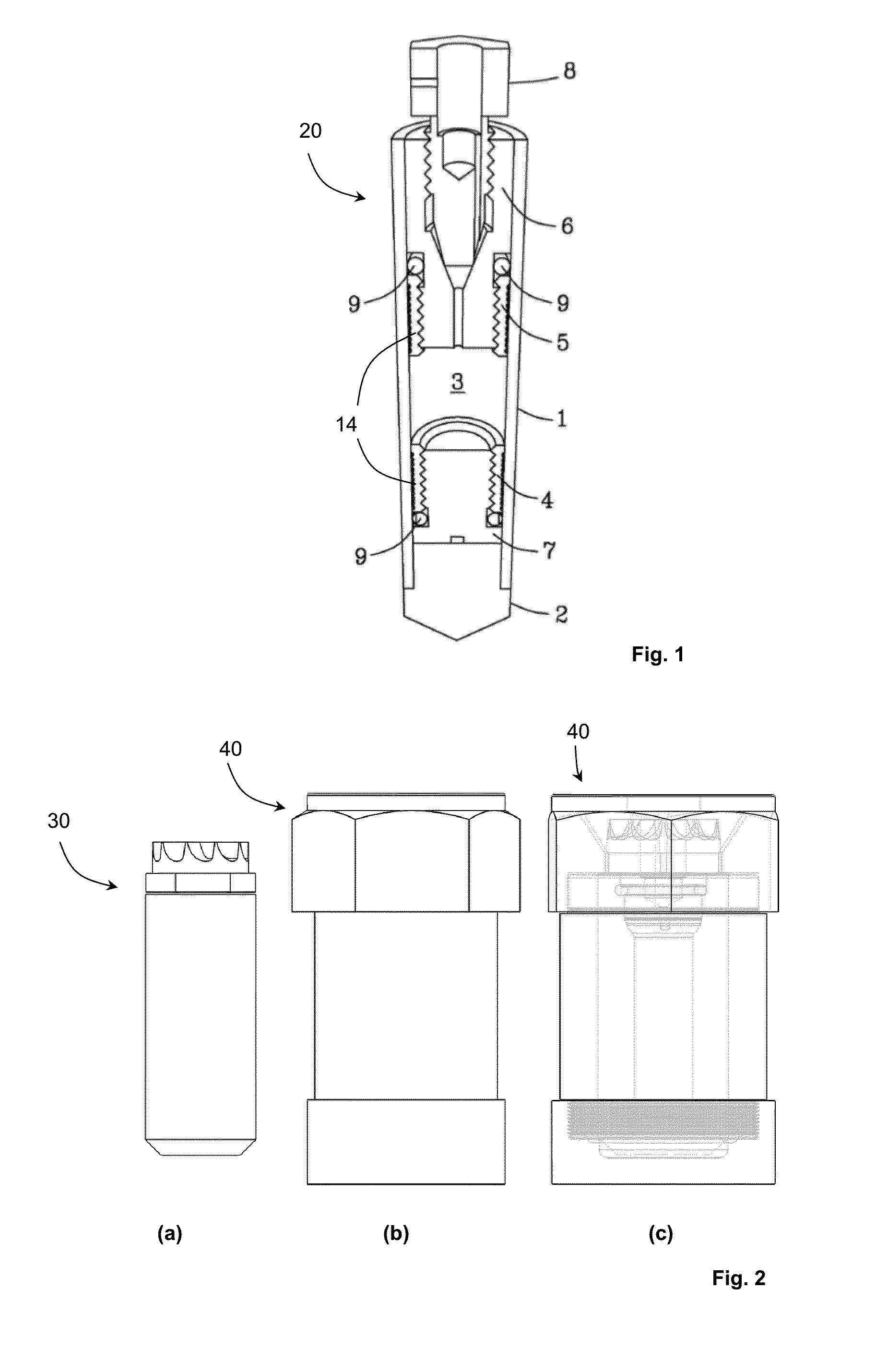
[0045]FIG. 2 illustrates a sample holder 30 according to an embodiment (FIG. 2(a)) and a sealing cell 40 (FIG. 2(b)) used with the sample holder. The sealing cell is used seal the sample holder 30 and to accommodate filling of the sample holder 30, as described in further detail below. FIG. 2(c) illustrates the manner in which the sample holder 30 is retained in the sealing cell 40.

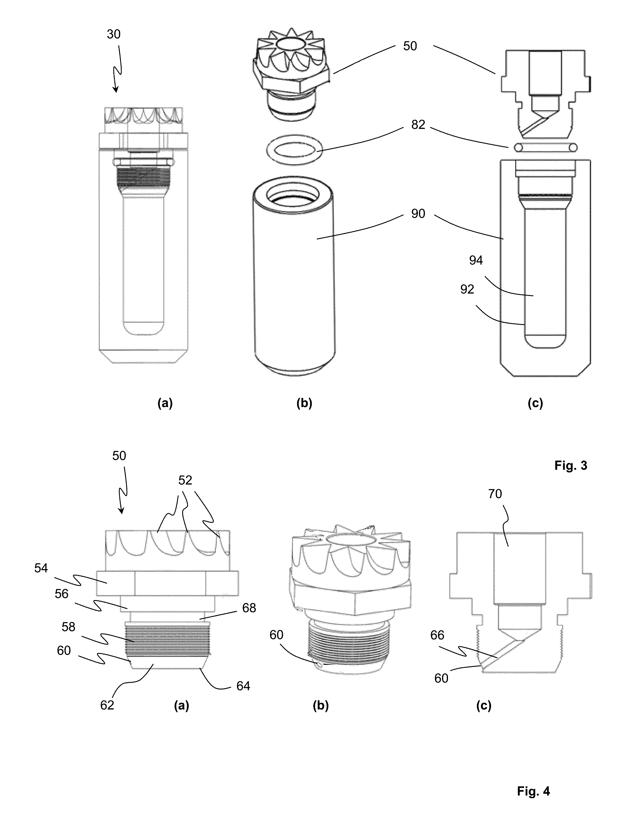
[0046]FIG. 3 illustrates an embodiment of the sample holder 30 of FIG. 2 in greater detail. The sample holder 30 (FIG. 3(a)) is shown in exploded view in FIGS. 3(b) and 3(c). As illustrated, the sample holder 30 comprises a plug 50, an O-ring 82 and a sample cell 90. The sample cell has an inner surface 92 which defines a sample volume 94 (FIG. 3(c)).

[0047]FIG. 4 illustrates an embodiment of the plug 50 in greater detail. Plug 50 is formed with rotor blades 52 used to drive rotation of the sample holder 30 in a known manner. A hexagonal (when viewed in axial plan) region 54 is formed between the blades 52...


PUM


Abstract

A sample holder for use with magic angle spinning NMR and similar magnetic resonance analysis techniques which includes a sample holder sealed by an O-ring and a contact seal. The O-ring seals the sample volume during pressurization whereas the contact seal is active during analysis. The O-ring and the contact seal are disposed so that rotation of a plug selective engages one or both of the seals.

Description

BACKGROUND[0001]1. Technical Field[0002]The present disclosure relates to sample holders including sample holders which may be used in analysis techniques such as magnetic resonance spectroscopy (MRS), magnetic resonance imaging (MRI) (e.g., magic angle spinning (MAS) nuclear magnetic resonance (NMR)), electron paramagnetic resonance (EPR), dynamic nuclear polarization (DNP), electron nuclear double resonance (ENDOR), etc.[0003]2. Description of the Related Art[0004]Both high resolution magic angle spinning (MAS) nuclear magnetic resonance (NMR) and electron paramagnetic resonance (EPR), as well as the combination of these (dynamic nuclear polarization (DNP) and electron-nuclear double resonance (ENDOR) are used for studying molecular structure and dynamics in samples which may be solid, semi-solid, or a heterogeneous mixture containing multiple phases. These are of particular interest in biophysics, such as protein investigations, catalysis analysis, geochemistry experiments, food ...

Claims


Application Information

Patent Timeline
Patent Type & Authority Applications(United States)
IPC IPC(8): G01R33/30
CPCG01R33/305G01R33/307
Inventor TURCU, ROMULUS VALERIU FLAVIUSIMON, SIMION
Owner UB2 INSTR SRL
Why Eureka
Try Eureka