
Mutual capacitive touch panel

A touch panel, mutual-capacity technology, applied in instruments, computing, electrical and digital data processing, etc., can solve the problems of consuming computing resources and processing time, the density of sensing coordinate points, and the burden on the processor, so as to improve the touch Accuracy, reduce the consumption of computing resources, reduce the effect of use

Active Publication Date: 2022-05-10
ILI TECHNOLOGY CORPORATION
View PDF5 Cites 0 Cited by
  • Summary
  • Abstract
  • Description
  • Claims
  • Application Information

AI Technical Summary

Problems solved by technology

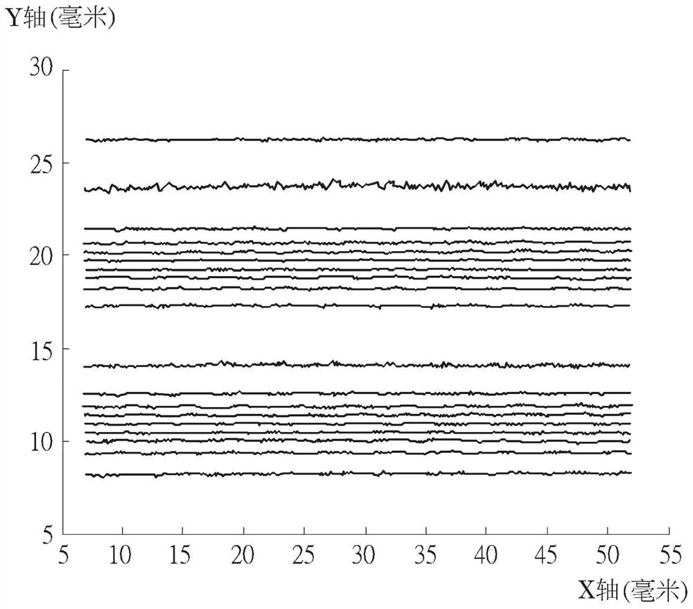
However, under this framework, when the touch object moves linearly along the Y-axis direction, the sensing coordinates sensed by the sensing series will have density.
In other words, when the touch object moves linearly along the X-axis direction at different positions on the Y-axis in an equidistant manner, the distances between the lines sensed by the induction series are not consistent, but the straight lines arranged along the Y-axis direction appear Alternate occurrence of density and density, resulting in inaccurate detection, such as figure 1 shown
Although this problem can be eliminated by algorithms, it takes computing resources and processing time, causing a burden on the processor

Method used


Image

  • Mutual capacitive touch panel
  • Mutual capacitive touch panel
  • Mutual capacitive touch panel

Examples


Embodiment Construction

[0045] In order to enable those skilled in the art to further understand the present invention, the embodiments of the present invention are enumerated below, together with the accompanying drawings, the constitutional content and desired effects of the present invention are described in detail. It should be noted that the drawings are all simplified schematic diagrams, therefore, only the components and combinations related to the present invention are shown to provide a clearer description of the basic structure of the present invention, but the actual components and layout may be more complicated. In addition, for the convenience of description, the elements shown in the drawings of the present invention are not drawn in proportion to the number, shape, and size of the actual implementation, and the detailed proportions can be adjusted according to design requirements.

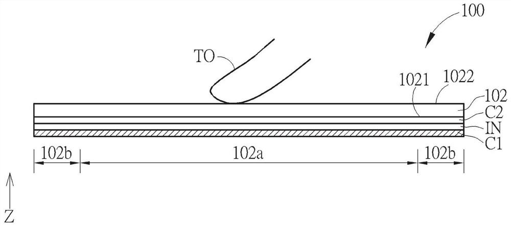
[0046] Please refer to figure 2 , which shows a schematic side view of the mutual capacitive touch pane...


PUM


Abstract

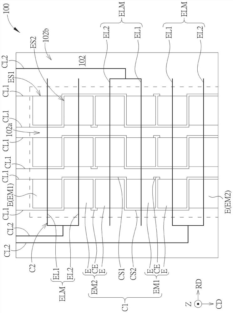
The invention discloses a mutual capacitive touch panel, which includes a first electrode layer and a second electrode layer. The first electrode layer includes a plurality of first electrode groups and a plurality of second electrode groups arranged in an array, the first electrode groups in the same row are electrically connected to form the first electrodes in series, and the second electrode groups in the same row are electrically connected Sexually connected to form the second electrode in series. The second electrode layer includes a plurality of electrode strip groups insulated from each other, which are arranged in sequence along the row direction of the array, wherein each electrode strip group extends along the column direction of the array and overlaps two adjacent columns in the vertical projection direction. electrode groups, and two adjacent electrode strip groups overlap the same row of electrode groups in the vertical projection direction.

Description

technical field [0001] The invention relates to a mutual capacitive touch panel, in particular to a mutual capacitive touch panel with double electrode layers. Background technique [0002] With the rapid development of science and technology, touch display devices composed of displays and touch panels can realize touch and display functions at the same time, and have the characteristics of human-computer interaction, and have been widely used in smart phones (smart phones), satellites, etc. Navigation system (GPS navigator system), tablet PC (tablet PC) and notebook computer (laptop PC) and other electronic products. Among them, the mutual capacitive touch panel has become the mainstream touch technology currently used in the industry due to its advantages of high accuracy, multi-touch, high durability, and high touch resolution. [0003] The mutual capacitive touch technology mainly judges the touch event by detecting the change of coupling capacitance between the static ...

Claims


Application Information

Patent Timeline
Patent Type & Authority Patents(China)
IPC IPC(8): G06F3/044
CPCG06F3/044
Inventor 许诚显洪国强江敬群郭玮伦丁鹏云
Owner ILI TECHNOLOGY CORPORATION
Learn More