Digital circuit device for demodulation blind area processing of high-frequency radio frequency identification chip

A technology for processing circuits and radio frequency identification. It is applied to record carriers, instruments, and computer parts used in machines. It can solve problems such as blind spots of radio frequency identification chips, decoding failures of demodulation digital circuits, and glitches in radio frequency output clocks.

Pending Publication Date: 2019-08-16
上海明矽微电子有限公司 +1
View PDF0 Cites 0 Cited by
  • Summary
  • Abstract
  • Description
  • Claims
  • Application Information

AI Technical Summary

Problems solved by technology

[0010] In reality, most demodulation analog circuits have poor performance. When the field strength of the card reader changes or the position of the card on the card reader is changed, the timing relationship between the RF output clock and the RF output data is different when each pause arrives. , the RF output clock output by it may also have glitches, which may cause the demodulation digital circuit to fail to decode, and the RFID chip will appear as a blind spot phenomenon

Method used


Image

  • Digital circuit device for demodulation blind area processing of high-frequency radio frequency identification chip
  • Digital circuit device for demodulation blind area processing of high-frequency radio frequency identification chip

Examples


Embodiment Construction

[0025] based on the following figure 1 and figure 2 , specifically illustrate the preferred embodiment of the device.

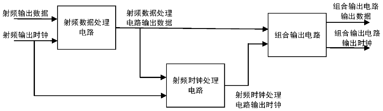
[0026] like figure 1 As shown, the connection relationship between the digital circuit device and the demodulation analog circuit and the demodulation digital circuit of the high-frequency radio frequency identification chip blind zone processing provided by the present invention, its input is the radio frequency output clock and radio frequency output data, and its output is the combined output circuit output data and combinational output circuit data clock. The radio frequency output clock and the radio frequency output data are outputs of the demodulation analog circuit, and the output data of the combination output circuit and the output clock of the combination output circuit are used as inputs of the demodulation digital circuit.

[0027] like figure 2 Shown is the structure and connection relationship of the digital circuit device for blind area ...


PUM


Abstract

The invention relates to a digital circuit device for demodulation blind area processing of a high-frequency radio frequency identification chip. The device comprises a radio frequency data processingcircuit which uses a radio frequency output clock to carry out sampling processing on radio frequency output data, so that a time sequence relation between the processed data and a clock is relatively fixed; a radio frequency clock processing circuit used for carrying out logic operation on the radio frequency output clock by using the output signal of the radio frequency data processing circuit,and a processed output clock signal which effectively avoids glitch; and a combined output circuit which performs logic operation on the output data and the output clock according to the logic requirements of the demodulation digital circuit on the clock signal and the data signal, so that the output signal of the combined output circuit meets the logic requirements of correct decoding of the demodulation digital circuit. The time sequence relation of the output data and the output clock processed by the device is stable, burrs on the clock can be effectively avoided, the requirement for stable work of a subsequent demodulation digital circuit can be met, and therefore the blind area phenomenon of a high-frequency radio frequency identification chip is effectively avoided.

Description

technical field [0001] The present invention belongs to the field of high-frequency radio frequency identification chips, specifically, belongs to the technical field of non-contact radio frequency chip demodulation circuits stipulated in the high-frequency radio frequency identification protocol, including but not limited to ISO14443-A, ISO-15693, MiFare1, ISO18092, NFC, etc. Background technique [0002] The high-frequency radio frequency identification chip mainly follows the protocols of ISO 14443, ISO-15693, MiFare1, ISO18092, NFC, etc. The protocol defines that its carrier frequency is 13.56MHz, and the sub-carrier frequency is 1 / 128 of the carrier frequency. The subcarrier will include a pause, and each subcarrier period represents 1 bit of data, and the position of the pause in a subcarrier period defines whether the data represented by the current subcarrier is 0 or 1. [0003] The card reader modulates the sub-carrier signal with the carrier frequency and sends it...

Claims


Application Information

Patent Timeline
IPC IPC(8): G06K19/07
CPCG06K19/0723
Inventor 张建伟左卫松
Owner 上海明矽微电子有限公司
Why Eureka
Try Eureka