Eureka AIR delivers breakthrough ideas for toughest innovation challenges, trusted by R&D personnel around the world.

Installing and fixing structure of voltage stabilizer for power system

A technology of power system and fixed structure, applied in substation/distribution device casing, substation/switchgear cooling/ventilation, electrical components, etc. Protective structure and other issues, to achieve the effect of easy installation and fixation, easy dustproof and heat dissipation, easy disassembly and replacement

Inactive Publication Date: 2019-08-16
MINJIANG UNIV
View PDF7 Cites 5 Cited by
  • Summary
  • Abstract
  • Description
  • Claims
  • Application Information

AI Technical Summary

Problems solved by technology

[0003] At present, most household voltage stabilizers on the market are fixed on the outer wall through bolts and mounting feet, and the installation and fixing effect is poor. The heat dissipation port of the regulator is blocked by dust after long-term use, which affects its normal heat dissipation and reduces its service life

Method used


Image

  • Installing and fixing structure of voltage stabilizer for power system
  • Installing and fixing structure of voltage stabilizer for power system
  • Installing and fixing structure of voltage stabilizer for power system

Examples


Embodiment Construction

[0024] The present invention will be further described below in conjunction with the accompanying drawings and specific embodiments.

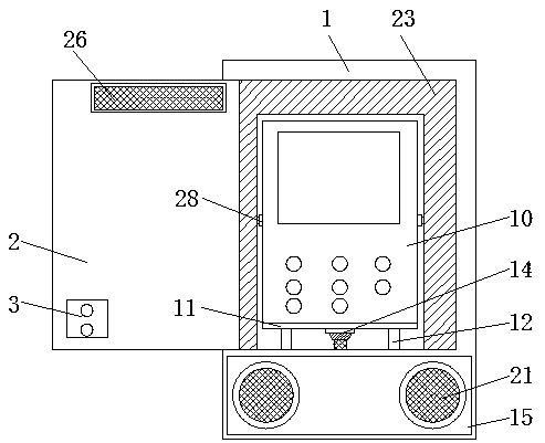
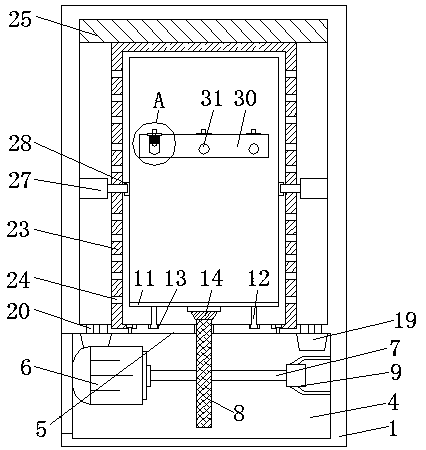
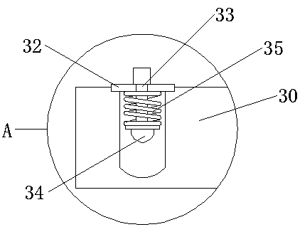
[0025] like Figure 1-6 As shown, an installation and fixing structure of a voltage stabilizer for a power system includes a cabinet for placing and installing the voltage stabilizer body, and the lower part of the cabinet is divided into an upper storage area and a lower accessory area by a horizontal plate. The front side of the cabinet body is provided with a cabinet door for opening and closing the storage area, the cabinet door is hinged with the cabinet body, the upper part of the cabinet door is provided with an air outlet, and a dust-proof net A is installed in the air outlet, and the lower part of the installation voltage stabilizer body A support plate is installed, and the lower part of the support plate is symmetrically arranged with a vertical slide plate, and the side of the horizontal plate is provided with a chute for accommodat...


PUM


Abstract

The invention relates to an installing and fixing structure of a voltage stabilizer for a power system. The installing and fixing structure comprises a cabinet body. The lower part in the cabinet bodyis divided into a storage area and a fitting area by a cross plate. A cabinet door is arranged on the front side of the cabinet body. The cabinet door is provided with an air outlet. A support plateis installed on the lower part of the voltage stabilizer body. The lower part of the support plate is provided with a slide plate. A slide groove for accommodating the slide plate is arranged on the cross plate. The left and right sides of the installing voltage stabilizer body are symmetrically provided with fixing blocks. An electric push rod for abutting against the fixing blocks is installed in the storage area. Air inlet holes communicated with the fitting area are arranged on the lower circumferential side of that cabinet body. A dust screen B and an exhaust fan are sequentially arrangedin the air inlet holes. A cover body A for covering the air inlet holes is installed in the fitting area. Drying cotton is installed in the cover body A. Ventilation holes are arranged on the cross plate. The lower end of the cross plate is provided with a cover body B for covering the ventilation holes. The cover body A is communicated with the cover body B through a ventilation pipe. The voltage stabilizer can be effectively installed and fixed, the voltage stabilizer can be effectively protected, disassembly and replacement are convenient and effective dust prevention and heat dissipationare convenient.

Description

technical field [0001] The invention relates to an installation and fixing structure of a voltage stabilizer used in a power system. Background technique [0002] The power system is mainly a power production and consumption system composed of power generation, power transformation, power transmission, power distribution and power consumption. Its function is to convert the natural primary energy into electric energy through power generation power devices (such as: boilers, steam turbines, generators, etc.), and then supply the electric energy to each load center through power transmission, power transformation system and power distribution system. Among them, the voltage stabilizers used in the power system can be roughly divided into two types: industrial applications and household applications. [0003] At present, most household voltage stabilizers on the market are fixed on the outer wall through bolts and mounting feet, and the installation and fixing effect is poor. ...

Claims


Application Information

Patent Timeline
Patent Type & Authority Applications(China)
IPC IPC(8): H02B1/36H02B1/38H02B1/42H02B1/44H02B1/28H02B1/56H02B1/54
CPCH02B1/28H02B1/36H02B1/38H02B1/42H02B1/44H02B1/54H02B1/565
Inventor 谭巧林文忠林东亮贺德华
Owner MINJIANG UNIV
Why Eureka
Eureka Blog
Learn More