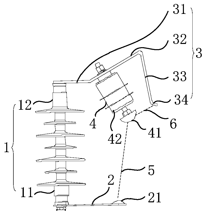
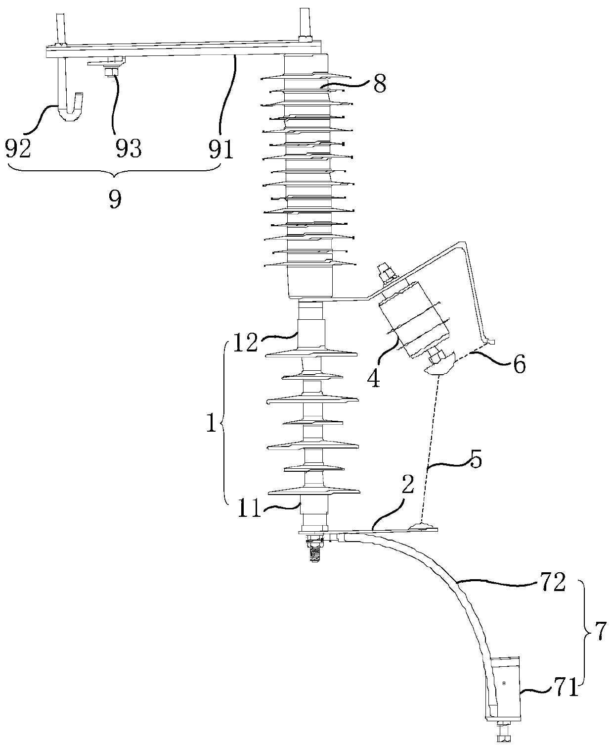
Discharge gap structure and discharge gap device without power-frequency freewheeling

A discharge gap and gap technology, applied in circuit devices, emergency protection circuit devices for limiting overcurrent/overvoltage, emergency protection circuit devices, etc., can solve problems such as single discharge gaps, endangering the normal operation of power distribution lines, etc. Achieve the effects of stable lightning protection performance, reduced dispersion, and improved lightning resistance level

Pending Publication Date: 2019-08-16
广州开能电气技术有限公司
View PDF0 Cites 0 Cited by
  • Summary
  • Abstract
  • Description
  • Claims
  • Application Information

AI Technical Summary

Problems solved by technology

However, the current non-power frequency freewheeling discharge gap device has the following disadvantages: the discharge gap structure of the non-power frequency freewheeling discharge gap device has a single discharge gap
When the energy generated by the overvoltage is large, the energy of the overvoltage cannot be completely released by the breakdown discharge of the gap, and the excess energy will still endanger the normal operation of the distribution line.

Method used


Image

  • Discharge gap structure and discharge gap device without power-frequency freewheeling
  • Discharge gap structure and discharge gap device without power-frequency freewheeling

Examples


Embodiment Construction

[0024] In order to make the above objects, features and advantages of the present invention more comprehensible, specific implementations of the present invention will be described in detail below in conjunction with the accompanying drawings. In the following description, numerous specific details are set forth in order to provide a thorough understanding of the present invention. However, the present invention can be implemented in many other ways different from those described here, and those skilled in the art can make similar improvements without departing from the connotation of the present invention, so the present invention is not limited by the specific implementations disclosed below.

[0025] It should be noted that when an element is referred to as being “fixed” to another element, it can be directly on the other element or there can also be an intervening element. When an element is referred to as being "connected to" another element, it can be directly connected ...


PUM


Abstract

The invention relates to a discharge gap structure and a discharge gap device without power-frequency freewheeling. The discharge gap structure comprises a support insulator, a discharge gap plate, anelectrode plate and a power-frequency current limiter. The support insulator comprises a first end and a second end which are disposed opposite to each other. The discharge gap plate is connected tothe first end of the support insulator, and is provided with a discharge gap top electrode. The electrode plate is connected to the second end of the support insulator. The power-frequency current limiter is fixedly connected to the electrode plate, and is provided with a discharge gap bottom electrode. A first discharge gap is formed between the discharge gap bottom electrode and the discharge gap top electrode. A second discharge gap is formed between the discharge gap bottom electrode and the electrode plate. The discharge gap device without power-frequency freewheeling provided by the invention can fully release the energy generated by overvoltage and improve lightning protection performance.

Description

technical field [0001] The invention relates to the technical field of high-voltage transmission line protection, in particular to a discharge gap structure and a non-power frequency freewheeling discharge gap device. Background technique [0002] When the distribution line (such as 35KV high-voltage distribution network and 110KV high-voltage distribution network) is overvoltage generated by lightning, it will cause flashover or breakdown of insulators and disconnection of wires. Lightning waves may even invade the substation along the distribution line, affecting the safe operation of the substation and even causing personal safety accidents. [0003] At present, in order to reduce the impact of overvoltage on distribution lines, discharge gap devices are generally installed on distribution lines. However, the current non-power-frequency freewheeling discharge gap device has the following disadvantages: the discharge gap structure of the non-power frequency freewheeling d...

Claims


Application Information

Patent Timeline
Patent Type & Authority Applications(China)
IPC IPC(8): H02H9/04H02H9/06
CPCH02H9/045H02H9/06
Inventor 徐卫东孙登峰邓玉本
Owner 广州开能电气技术有限公司
Why Eureka
Try Eureka