Crushing cavity wear monitoring method

A crushing cavity and wear rate technology, applied in testing/monitoring control systems, instruments, control/regulating systems, etc., can solve the problems of inability to monitor and detect local area features, high wear rates, and high operating costs of crushers, reducing The effect of crusher failure

Active Publication Date: 2022-02-22
JIANGXI UNIV OF SCI & TECH
View PDF10 Cites 0 Cited by
  • Summary
  • Abstract
  • Description
  • Claims
  • Application Information

AI Technical Summary

Problems solved by technology

[0016] The purpose of the embodiments of the present invention is to provide a crushing chamber wear monitoring method and its monitoring structure, which aims to solve the problem that the existing technology cannot update and predict the life of the liner according to the dynamic use of the crusher, and cannot predict the wear of the liner that is about to reach the wear limit in advance. Replacement or maintenance of the board, unable to monitor and detect the characteristics of local areas between nodes, and the crusher has technical problems such as high operating costs and high wear rates

Method used


Image

  • Crushing cavity wear monitoring method
  • Crushing cavity wear monitoring method
  • Crushing cavity wear monitoring method

Examples


Embodiment 1

[0091] A service node for monitoring a crushing chamber comprising:

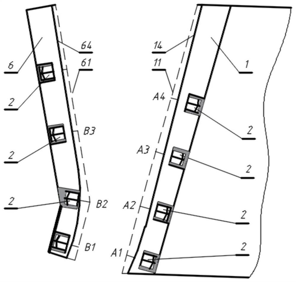
[0092] Calculation equipment for calculating the measured liner thickness at each detection node at different positions in the crushing cavity;

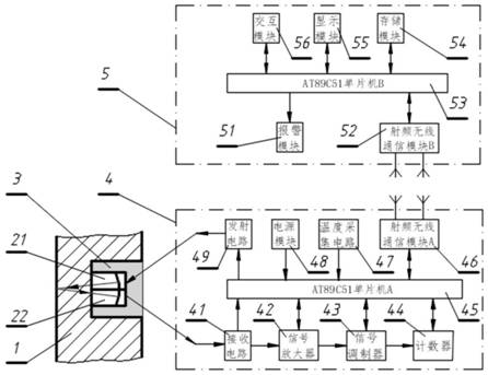
[0093] The computing device includes a host computer and an ultrasonic ranging and transmission module, and the host computer is connected to the ultrasonic ranging sensor in the detection node through the ultrasonic ranging and transmitting module.

[0094] The ultrasonic ranging and transmission module 4 includes a first single-chip microcomputer 45 and a first radio frequency wireless communication module 46, and the host computer 5 includes a second single-chip microcomputer 53 and a second radio frequency wireless communication module 52, and the first single-chip microcomputer 45 and the first radio frequency wireless communication module 52 The second single-chip microcomputer 53 performs wireless communication through the first radio frequency wireless comm...

Embodiment 2

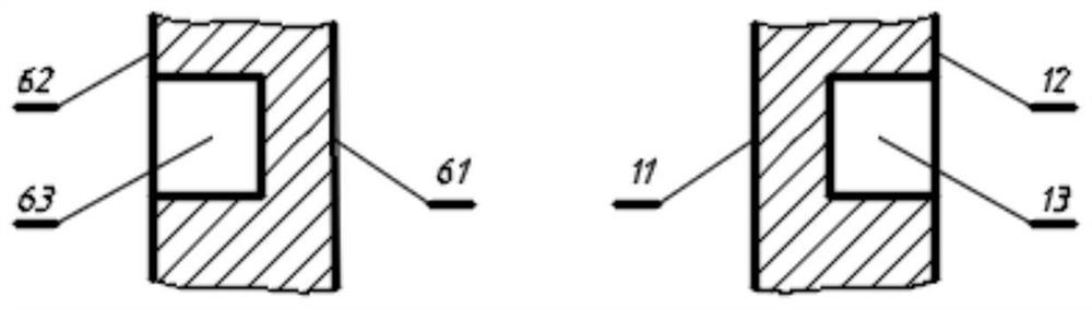
[0117] Based on Example 1, such as figure 1 As shown, the present invention discloses an intelligent liner, including a movable cone liner 1 , a fixed cone liner 6 , an ultrasonic ranging sensor 2 , a coupling agent 3 , an ultrasonic ranging and transmission module 4 and a host computer 5 . The ultrasonic ranging sensor 2 is composed of a transmitting chip 21 and a receiving chip 22. The ultrasonic ranging sensor 2 is installed in the blind hole 13 on the side of the non-working surface of the lining plate 1, and in the blind hole 1 of the lining plate 1 13 is filled with coupling agent 3 between the ultrasonic distance measuring sensor 2, the transmitting chip 21 of the ultrasonic ranging sensor 2 is connected with the transmitting circuit 49 of the ultrasonic ranging and transmission module 4, and the ultrasonic ranging sensor 2 The receiving chip 22 is connected to the receiving circuit 41 of the ultrasonic ranging and transmission module 4, and the host computer 5 is conne...


PUM


Abstract

An embodiment of the present invention provides a crushing cavity wear monitoring method, which belongs to the technical field of crushing equipment operation status monitoring. The crushing cavity wear monitoring method includes: obtaining feedback signals having cavity shape characteristics of the crushing cavity at each detection node at different positions of the crushing cavity, and proceeding to the next step when the feedback signals meet the first preset monitoring condition; Select the current detection node, and determine the crushing cavity’s size based on the distance between the current detection node and the adjacent detection node, the feedback signal corresponding to the current detection node, and the feedback signal corresponding to the adjacent detection node. Local characteristics of the cavity shape; when the wear rate corresponding to the local characteristics of the cavity shape satisfies the second preset monitoring condition, jump to the second step to form a cyclic monitoring process. The invention monitors the wear condition of the lining plate and the change of the structural shape of the crushing cavity by detecting the characteristics at the position and the current detection local area characteristics, can predict the working life of the lining plate and create conditions for reasonably formulating the operation and maintenance plan of the crusher.

Description

technical field [0001] The invention relates to the technical field of crushing equipment operation status monitoring, in particular to a crushing cavity wear monitoring method and a monitoring structure thereof. Background technique [0002] The working mechanism of the crusher is composed of a fixed liner and a movable liner, and the area between the working surfaces is the crushing chamber. During the crushing process, the movable liner swings according to a certain rule relative to the fixed liner to crush the material in the crushing cavity, making the particle size of the material continuously smaller until it is discharged out of the crushing cavity. [0003] During the crushing process, the materials in the crushing cavity will wear the fixed liner and the movable liner, and this wear will change the shape of the crushing cavity, resulting in the deterioration of the crushed product quality. There are two main methods for evaluating the amount of liner wear and its ...

Claims


Application Information

Patent Timeline
Patent Type & Authority Patents(China)
IPC IPC(8): B02C2/00B02C23/00B02C25/00
CPCB02C2/00B02C23/00B02C25/00G05B23/0218B02C2210/01
Inventor 蔡改贫罗小燕刘鑫胡显能陈浩华
Owner JIANGXI UNIV OF SCI & TECH
Why Eureka
Try Eureka