Fault detection method and device for a swing door

A technology of fault detection and detection devices, which is applied in metal rolling, metal processing equipment, bending workpieces, etc., can solve the problems of long response time and untimely response, and achieve the effect of reducing response time

Active Publication Date: 2021-02-26
SHOUGANG JINGTANG IRON & STEEL CO LTD
View PDF8 Cites 0 Cited by
  • Summary
  • Abstract
  • Description
  • Claims
  • Application Information

AI Technical Summary

Problems solved by technology

[0004] In view of this, the purpose of the embodiment of the present invention is to provide a swing door fault detection method and device, which solves the problems of untimely and long response time in the current swing door fault detection method

Method used


Image

  • Fault detection method and device for a swing door
  • Fault detection method and device for a swing door
  • Fault detection method and device for a swing door

Examples


no. 1 example

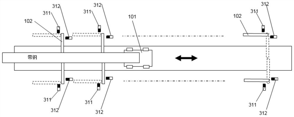
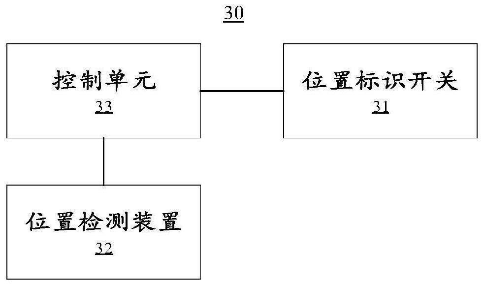
[0048] Please refer to figure 1 with figure 2 , figure 1 It shows an application scene diagram of a swing door fault detection device 30 provided in this embodiment. In this embodiment, a swing door fault detection device 30 is provided, which includes: a position identification switch 31, a position detection device 32 and control unit 33.

[0049] In the present embodiment, the position identification switch 31 is arranged on the running track of the swing door 102, the position detection device 32 is arranged on the looper trolley 101, and the control unit 33 is coupled with the position detection device 32 and the position identification switch 31 respectively, and obtains the position The data collected by the detection device 32 and the position identification switch 31.

[0050] Specifically, in the swing door fault detection device 30 in this embodiment:

[0051] The position identification switch 31 is used to detect the real-time state of opening or closing of t...

no. 2 example

[0074] In this embodiment, a swing door fault detection method is provided, the method comprising:

[0075] Obtain the opening or closing state signal of the swing door; obtain the real-time position of the looper trolley; judge whether the state signal of the swing door matches the real-time position of the looper trolley; if not, generate a fault alarm signal.

[0076] As an optional implementation manner, obtaining the open or closed state signal of the swing door includes: obtaining an open signal when detecting that the swing door is in an open state; obtaining a close signal when detecting that the swing door is in a closed state.

[0077] As an optional implementation, the real-time position of the looper car is any of the following:

[0078] The first interval where the open position marks the swing door cannot be detected by the switch when it is flushing;

[0079] The closed position marks the second section where the switch can detect the swing door when it is flus...

no. 3 example

[0095] Based on the same inventive idea, such as Figure 4 As shown, this embodiment provides a computer-readable storage medium 500, on which a computer program 511 is stored, and when the computer program 511 is executed by a processor, the following steps are implemented:

[0096] Obtain the opening or closing state signal of the swing door; obtain the real-time position of the looper trolley; judge whether the state signal of the swing door matches the real-time position of the looper trolley; if not, generate a fault alarm signal.

[0097] In a specific implementation process, when the computer program 511 is executed by the processor, any implementation manner in the first embodiment (or the second embodiment) may be implemented, which will not be repeated here.


PUM


Abstract

The embodiment of the invention provides a swing door fault detection method and device. The swing door fault detection device comprises a position identification switch, a position detection device and a control unit. The position identification switch is used for detecting a real-time state of opening or closing of a swing door and generating a state signal of the swing door; the position detection device is used for detecting a real-time position of a loop trolley; the control unit is used for judging whether the state signal of the swing door is matched with the real-time position of the loop trolley or not; and if not, a fault alarm signal is generated. The method and device solve the problems that an existing swing door fault detection method is not timely and long in response time.

Description

technical field [0001] The invention relates to the technical field of steel rolling, in particular to a swing door fault detection method and device. Background technique [0002] The looper swing door is mainly used to support the strip steel in the punching process. The swing door has two operating states, namely open state and closed state. When the swing gate is closed, it can be used to support the strip steel, and when it is open, it can pass the looper trolley smoothly. The open state and closed state of the swing door are detected by the position indicator switch. The looper trolley has been in dynamic cooperation with many swing doors for a long time, and the strip steel with poor plate shape has a disturbing effect on the idler rollers of the swing door, which causes the shift of the locking position of the swing door, thus causing the looper trolley to easily contact with the swing door. The collision caused a production accident. [0003] However, the respon...

Claims


Application Information

Patent Timeline
Patent Type & Authority Patents(China)
IPC IPC(8): B21B41/12B21B41/00
CPCB21B41/00B21B41/12
Inventor 吉志明王艳超孙抗马龙王慧宇沈福磊张益滔常生财肖激杨
Owner SHOUGANG JINGTANG IRON & STEEL CO LTD
Why Eureka
Try Eureka