Historical block live-action modeling data collecting device

A technology of real scene modeling and data acquisition, which is applied in the direction of camera devices, etc., can solve problems such as the inability to automatically adjust the height of the shooting and collecting devices, and the failure of camera and collecting equipment, so as to improve convenience and practicability, improve convenience, and facilitate operation Effect

Pending Publication Date: 2019-08-20
YANGZHOU POLYTECHNIC INST
View PDF0 Cites 1 Cited by
  • Summary
  • Abstract
  • Description
  • Claims
  • Application Information

AI Technical Summary

Problems solved by technology

[0002] The street view acquisition process is to install the specially developed information collection equipment and automatic processing software on the information collection vehicle. As long as the collection vehicle drives by at a certain speed, the panorama will be accurately captured, and then af

Method used


Image

  • Historical block live-action modeling data collecting device
  • Historical block live-action modeling data collecting device
  • Historical block live-action modeling data collecting device

Examples


Embodiment 1

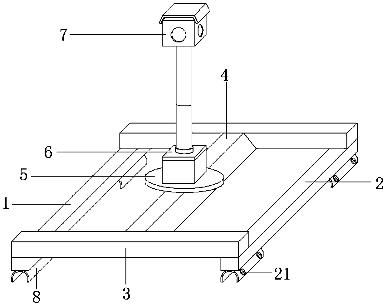
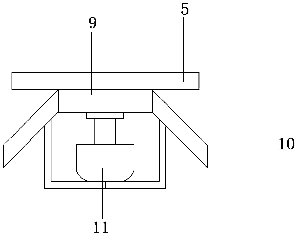
[0020] Such as Figure 1-Figure 4 As shown, a historical block real-scene modeling data acquisition device includes a first base plate 1, a second base plate 2 is provided on the right side of the first base plate 1, and the top of the first base plate 1 and the second base plate 2 are symmetrically connected with Fixed plates 3, mounting seats 4 are connected between the fixed plates 3, a chassis 5 is provided at the bottom of the mounting seats 4, a first operation box 6 is fixedly connected to the top of the chassis 5, and the top of the first operation box 6 There is a second operation box 7, the bottoms of the first bottom plate 1 and the second bottom plate 2 are symmetrically provided with connectors 8 respectively, and the mounting seat 4 includes a horizontal plate 9, and the left sides of the horizontal plate 9 are symmetrically connected with The baffle plate 10, the bottom of the horizontal plate 9 is fixedly connected with the rotating motor 11, and the rotating m...

Embodiment 2

[0026] Such as figure 1 As shown, the bottom of the connecting piece 8 is provided with an arc-shaped groove, and the outer side of the connecting piece 8 is symmetrically connected with fixing bolts 21, so that the four connecting pieces 8 can be engaged with the luggage on the roof of the car through the arc-shaped groove. On the frame, the fixing bolt 21 can pass through the connecting piece 8 and abut against the luggage rack, which can effectively improve the stability of the overall device and avoid shaking of the data acquisition device itself during the operation of the vehicle.

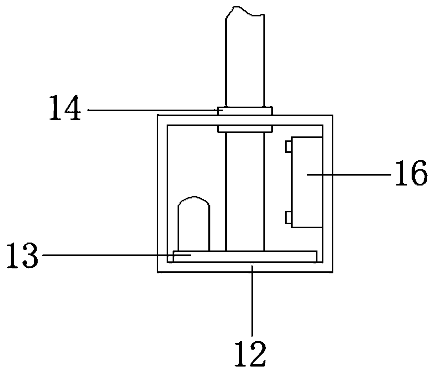
[0027] When the present invention is in use, the four connectors 8 are engaged on the roof rack of the car through arc grooves, and the rotating motor 11 and the electric push rod 13 are respectively controlled in the car. When the rotating motor 11 is started, the rotating motor The output end of 11 is connected to the chassis 5, so that the rotating motor 11 can drive the chassis 5 to rotat...


PUM


Abstract

The invention relates to a historical block live-action modeling data collecting device which comprises a first bottom plate. A second bottom plate is arranged on the right side of the first bottom plate. Fixed plates are symmetrically connected with the top of the first bottom plate and the second bottom plate. A mounting seat is connected between the fixed plates. A chassis is arranged at the bottom of the mounting seat. The top of the chassis is fixedly connected with a first operation box. A second operation box is arranged at the top of the first operation box. Connecting members are symmetrically arranged at the bottom of the first bottom plate and the second bottom plate. The mounting seat comprises a horizontal plate. Baffles are symmetrically connected with both sides of the leftside of the horizontal plate. The bottom of the horizontal plate is fixedly connected with a rotating electric machine. The first operation box comprises a first box body, which further improves the convenience and the practicability. The operation is more convenient, so that a camera body can more conveniently capture the panoramic view of a building block. People do not need to manually performtargeted shooting and collecting one by one, which extends the service life of the camera body.

Description

technical field [0001] The invention relates to a real-scene modeling data acquisition device for historical blocks, and belongs to the technical field of modeling data acquisition equipment. Background technique [0002] The street view acquisition process is to install the specially developed information collection equipment and automatic processing software on the information collection vehicle. As long as the collection vehicle drives by at a certain speed, the panorama will be accurately captured, and then after the later development and production, Three-dimensional visual effects can appear, but the height of the existing shooting and acquisition devices cannot be automatically adjusted, and people need to manually operate the camera when shooting panoramas. A data acquisition device for block reality modeling. Contents of the invention [0003] The technical problem to be solved by the present invention overcomes the existing defects, and provides a real-scene mod...

Claims


Application Information

Patent Timeline
IPC IPC(8): G01C11/02
CPCG01C11/02
Inventor 王晴张燕王冲张军张静
Owner YANGZHOU POLYTECHNIC INST
Why Eureka
Try Eureka