
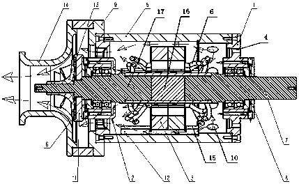
Self-heat-extraction cooling structure for high-speed motor

A high-speed motor and cooling structure technology, applied in the direction of cooling/ventilation devices, electrical components, electromechanical devices, etc., can solve problems such as poor heat dissipation, motor performance degradation, and permanent magnet effects, so as to improve stability and safety, improve Heat dissipation effect, effect of changing heat dissipation and cooling problems

Pending Publication Date: 2019-08-20
QUANZHOU HUADE ELECTROMECHANICAL EQUIP
View PDF0 Cites 3 Cited by
  • Summary
  • Abstract
  • Description
  • Claims
  • Application Information

AI Technical Summary

Problems solved by technology

[0003] At present, the commonly used high-speed motors use water pumps as surface cooling circulation systems, which require separate water pumps and heat dissipation systems. The structure is relatively complicated, and the heat dissipation of the rotor shaft and bearings is not very ideal. The rotor shaft and bearings The heat dissipation is related to the stability and reliability of the overall motor operation. Poor heat dissipation of the rotor shaft and bearings during high-speed operation will cause thermal expansion of the rotor shaft and bearings, resulting in unbalance of the main shaft and changes in the bearing clearance, and the rotor shaft uses permanent magnets. , high-speed operation will cause the rotor shaft to heat up. Without cooling, it will have a great impact on the permanent magnets, and will cause serious demagnetization of the permanent magnets, resulting in a decline in motor performance. Therefore, the heat dissipation of the rotor shaft and bearings is related to the overall reliability. Therefore, we propose a self-extraction heat cooling structure for high-speed motors

Method used


Image

  • Self-heat-extraction cooling structure for high-speed motor

Examples


Embodiment Construction

[0014] The following will clearly and completely describe the technical solutions in the embodiments of the present invention with reference to the accompanying drawings in the embodiments of the present invention. Obviously, the described embodiments are only some, not all, embodiments of the present invention. Based on the embodiments of the present invention, all other embodiments obtained by persons of ordinary skill in the art without making creative efforts belong to the protection scope of the present invention.

[0015] In the description of the application, it should be noted that, unless otherwise clearly specified and limited, the terms "installed", "installed", "connected", etc. should be understood in a broad sense, such as "connected", which may be a fixed connection, It can also be a detachable connection or an integral connection; it can be a mechanical connection or an electrical connection; it can be a direct connection or an indirect connection through an int...


PUM


Abstract

The invention discloses a self-heat-extraction cooling structure for a high-speed motor. The structure comprises a front end cover, a rear end cover, a shell and an air outlet shell, wherein an air hole groove is formed in the inner surface of the front end cover, the middle ends of the inner surfaces of the front end cover and the rear end cover are respectively movably connected with a first rotor shaft and a second rotor shaft through bearings, stators are arranged on the outer surfaces of the first rotor shaft and the second rotor shaft, and a magnetic steel is arranged between the first rotor shaft and the second rotor shaft. The air hole groove is formed in the inner surface of the front end cover; through the action of the outer shell, a fixing plate in the wind shell, an impeller and a notch, the temperature of the rotor shaft and the bearing can be controlled within a range which does not affect operation, thereby improving the stability and the safety of the whole machine. Meanwhile, the structure can solve the problems of heat dissipation and cooling of the stator, the rotor and the bearing of the high-speed motor without changing the structure of the high-speed motor, and the temperature rise of the high-speed motor can be reduced without additional equipment.

Description

technical field [0001] The invention relates to the technical field of motors, in particular to a self-extraction heat cooling structure for high-speed motors. Background technique [0002] The motor is a device that converts electrical energy into mechanical energy. It uses the energized coil (that is, the stator winding) to generate a rotating magnetic field and acts on the rotor (such as a squirrel-cage closed aluminum frame) to form a magnetoelectric power rotation torque. The motor uses the power supply Differently divided into DC motors and AC motors, most of the motors in the power system are AC motors, which can be synchronous motors or asynchronous motors (the magnetic field speed of the motor stator and the rotational speed of the rotor do not maintain synchronous speed), and the motor is mainly composed of a stator and a rotor , The direction of the force-moving wire in the magnetic field is related to the direction of the current and the direction of the magnetic...

Claims


Application Information

Patent Timeline
Patent Type & Authority Applications(China)
IPC IPC(8): H02K5/20H02K9/06
CPCH02K5/20H02K9/06
Inventor 黄俊峰
Owner QUANZHOU HUADE ELECTROMECHANICAL EQUIP
Learn More