Material shifting and discharging device of straightening machine

A discharge device and straightening machine technology, applied in the field of straightening machines, can solve the problems of low efficiency of manual loading and unloading operations, cost consumption of enterprises, high work intensity, etc. The effect of stable material output

Inactive Publication Date: 2019-08-23
SHANDONG RONGTAI ELECTRIC FURNACE ENGINEER
View PDF0 Cites 0 Cited by
  • Summary
  • Abstract
  • Description
  • Claims
  • Application Information

AI Technical Summary

Problems solved by technology

[0003] The current loading and unloading basically adopts the method of manual loading and unloading. Since the position of the driven roller needs to be adjusted, if the worker is negligent in operation, it is easy to be crushed by the straightening roller, and the efficiency of manual loading and unloading operation is very low, and the work intensity is high. , which also brings huge cost consumption to the enterprise

Method used


Image

  • Material shifting and discharging device of straightening machine
  • Material shifting and discharging device of straightening machine
  • Material shifting and discharging device of straightening machine

Examples


Embodiment Construction

[0021] In order to facilitate the understanding of those skilled in the art, the present invention will be further described below in conjunction with the accompanying drawings.

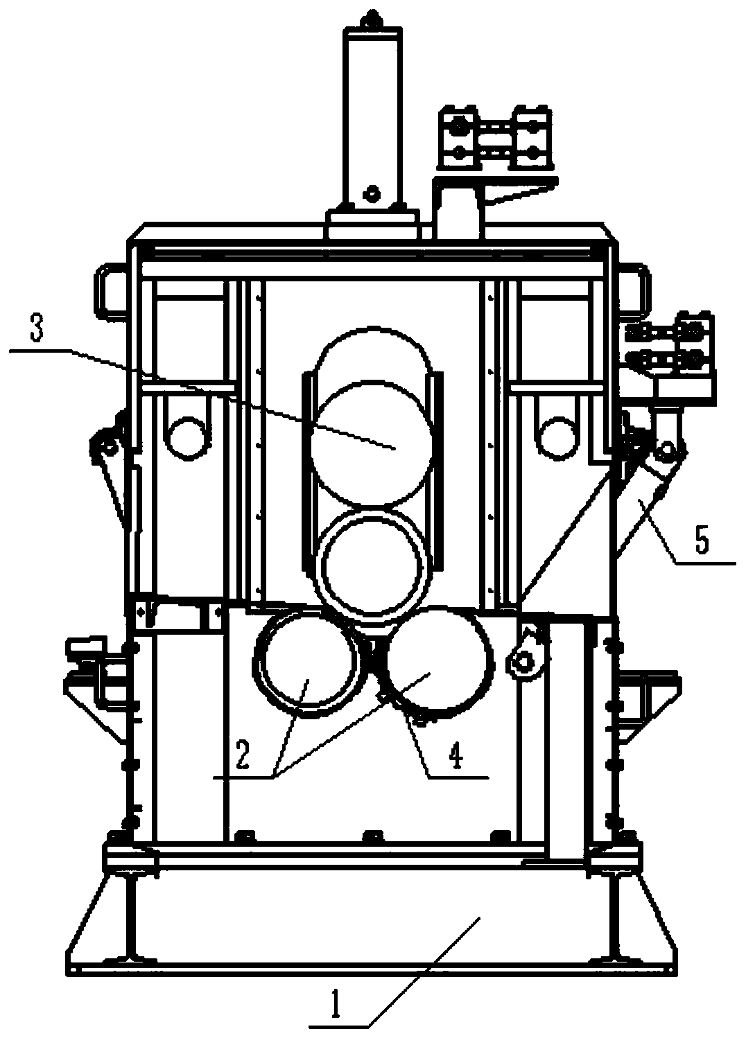
[0022] Such as Figure 1 to Figure 3 As shown, a straightening machine dialing and discharging device includes a straightening machine body 1. There are three straightening rollers distributed in a triangle on the straightening machine body 1 of the present invention, and the three straightening rollers are respectively set at the top The position-adjustable driven roller 3 and the two driving rollers 2 arranged below, the driven roller 3 of the present invention can realize lifting movement, while the two driving rollers 2 can only realize rotation;

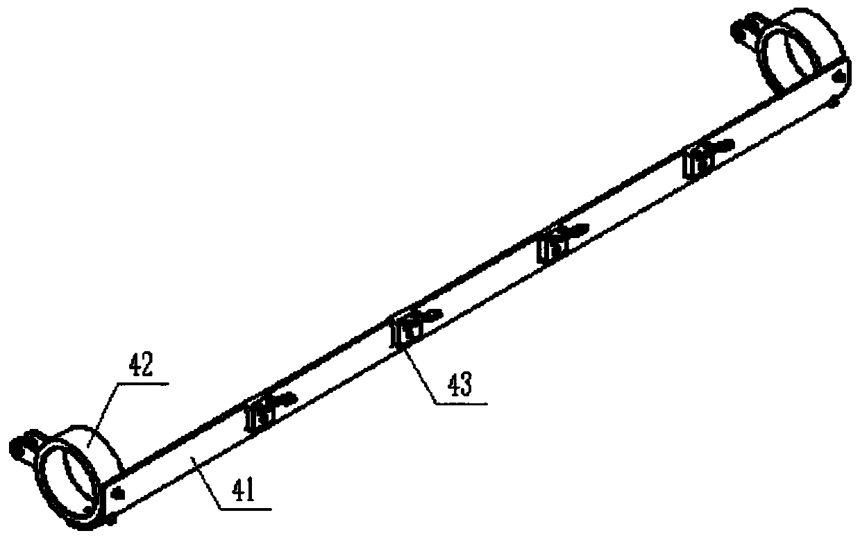
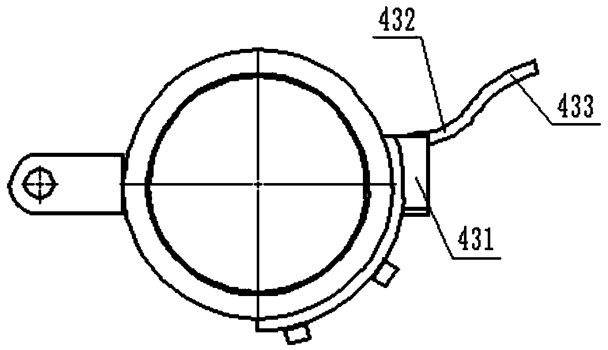
[0023] The driving roller 2 on the discharge side is provided with a material driving device 4, the material driving device 4 includes a material driving rod 41, the material driving rod 41 is evenly distributed with a material driving piece 43, and th...


PUM


Abstract

The invention discloses a material shifting and discharging device of a straightening machine and belongs to the field of straightening machines. The material shifting and discharging device comprisesa straightening machine body. The straightening machine body is provided with three straightening rolls distributed in a triangle mode. The three straightening rolls include the position adjustable driven roll arranged on the uppermost portion and the two driving rolls arranged below. A material shifting device is arranged on the driving roll on the discharge side. The material shifting device comprises a shifting rod. Shifting plates are uniformly distributed on the shifting rod. The two ends of the shifting rod are provided with rotary rings arranged at the two ends of the driving roll on the discharge side in a sleeving mode. The rotary rings are connected with a driving device. The driving device drives the rotary rings and the shifting rod to rotate around the driving roll on the discharge side. The shifting plates are arranged between the two driving rolls. Each shifting plate comprises a connecting plate, a transition plate and a shift-out plate which are integrally arranged, and the connecting plate is connected with the shifting rod. The driving roll on the feed side is provided with a plurality of grooves. The number and positions of the grooves correspond to those of the shift-out plates. The shift-out plates can be hidden in the grooves. The rotary rings rotate to drive the shift-out plates to be pulled out from the grooves.

Description

technical field [0001] The invention relates to the field of straightening machines, in particular to a straightening machine pulling and discharging device. Background technique [0002] Columnar or tubular structures may be bent during production or transfer, so they must be straightened by a straightening machine. Straightening cylindrical or tubular parts generally requires three straightening rollers, usually two driving rollers and one Driven roller, in order to facilitate loading and unloading, the driven roller is often set in a structure with adjustable position; [0003] The current loading and unloading basically adopts the method of manual loading and unloading. Since the position of the driven roller needs to be adjusted, if the worker is negligent in operation, it is easy to be crushed by the straightening roller, and the efficiency of manual loading and unloading operation is very low, and the work intensity is high. , It also brings huge cost consumption to ...

Claims


Application Information

Patent Timeline
Patent Type & Authority Applications(China)
IPC IPC(8): B21D3/02B21D45/02
CPCB21D3/02B21D45/02
Inventor 李莉丽殷志胜
Owner SHANDONG RONGTAI ELECTRIC FURNACE ENGINEER
Why Eureka
Try Eureka