Control device of machine tool ejector pin stroke

A control device and machine tool technology, which is applied to manufacturing tools, tool holder accessories, tailstocks/tops, etc., can solve the problems of inaccurate expansion and contraction and potential safety hazards, and achieve the effect of solving potential safety hazards.

Inactive Publication Date: 2019-08-23
ANHUI JIANGHUAI AUTOMOBILE GRP CORP LTD
View PDF8 Cites 0 Cited by
  • Summary
  • Abstract
  • Description
  • Claims
  • Application Information

AI Technical Summary

Problems solved by technology

[0005] The main purpose of the present invention is to propose a control device for machine tool thimble travel, aiming at solving the problems of inaccurate expansion and contraction and potential safety hazards when the existing machine tool thimbles are manually operated to expand and contract.

Method used


Image

  • Control device of machine tool ejector pin stroke
  • Control device of machine tool ejector pin stroke
  • Control device of machine tool ejector pin stroke

Examples


Embodiment Construction

[0042] The following will clearly and completely describe the technical solutions in the embodiments of the present invention with reference to the accompanying drawings in the embodiments of the present invention. Obviously, the described embodiments are only part of the embodiments of the present invention, not all of them. Based on the embodiments of the present invention, all other embodiments obtained by persons of ordinary skill in the art without creative efforts fall within the protection scope of the present invention.

[0043] It should be noted that if there is a directional indication (such as up, down, left, right, front, back...) in the embodiment of the present invention, the directional indication is only used to explain the position in a certain posture (as shown in the accompanying drawing). If the specific posture changes, the directional indication will also change accordingly.

[0044] In addition, if there are descriptions involving "first", "second" and ...


PUM


Abstract

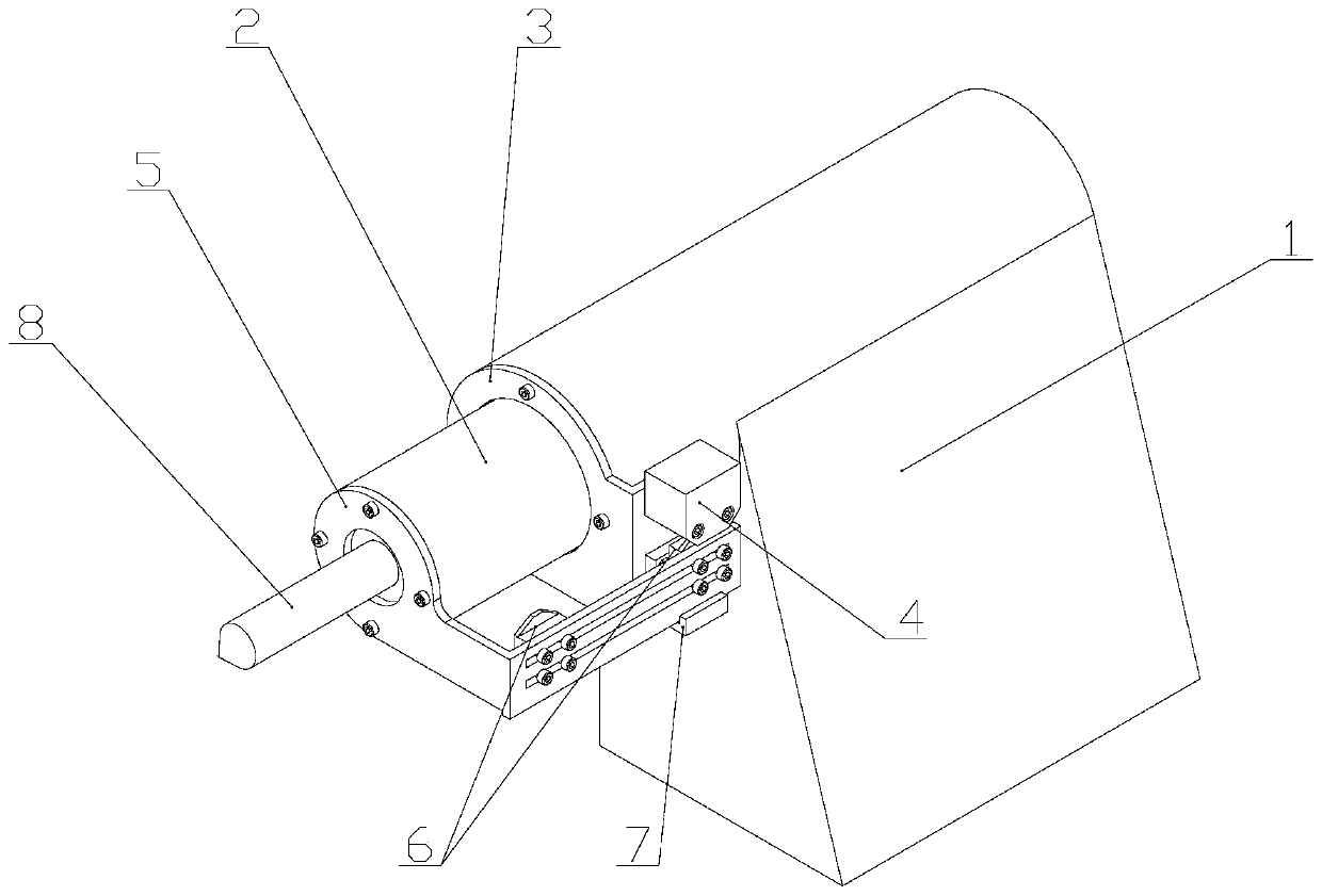
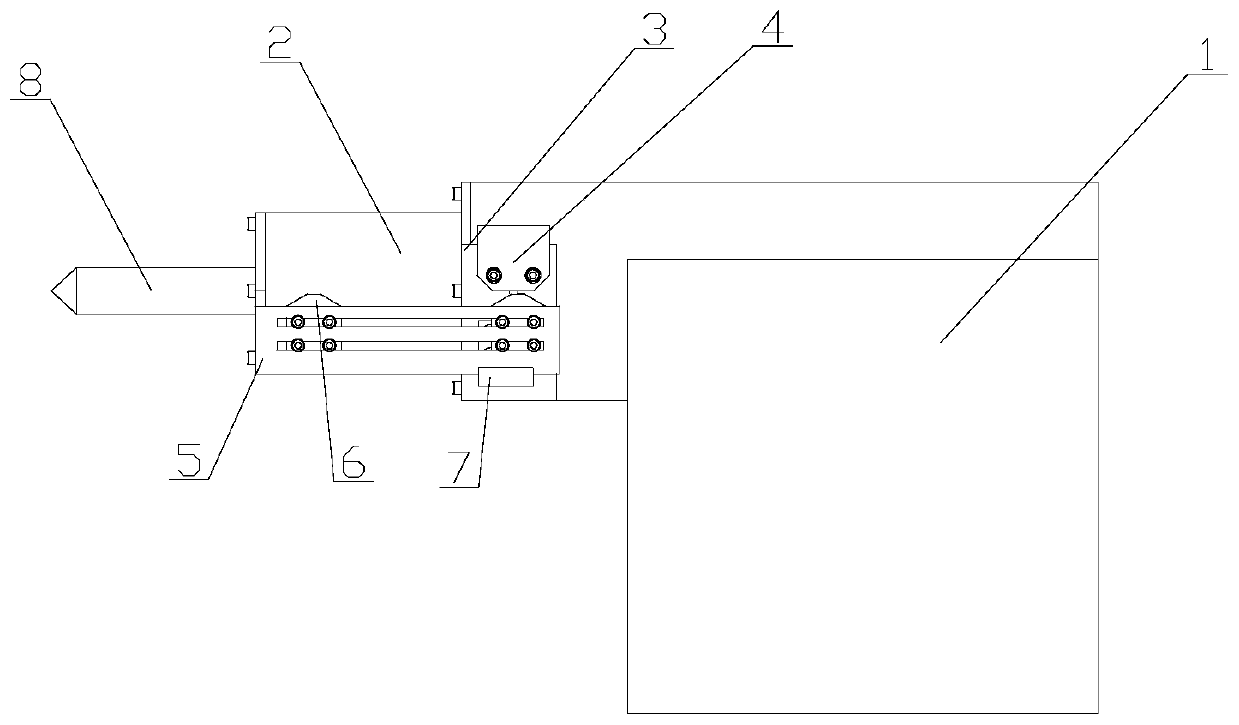
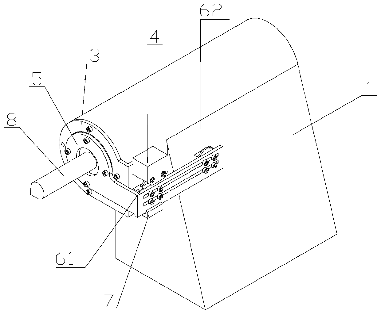
The invention discloses a control device of machine tool ejector pin stroke, and relates to the technical field of mechanical machining equipment. The control device of the machine tool ejector pin stroke is used for a machine tool ejector pin and comprises a machine tool base, a machine tool piston, a sensor, and two contact switches. The machine tool piston does telescopic motion on a machine tool in the length direction, the top end of the machine tool piston is connected with the ejector pin, the sensor is fixed to one side of the machine tool base through a sensor mounting support, the contact switches are arranged on one side of the machine tool base through a contact switch support, and stretch out and draw back along with the machine tool piston, and the contact switches are matched with the sensor, and control the extending limit and the shrinkage limit of the ejector pin on the machine tool piston. According to the control device of machine tool ejector pin stroke, the traditional manual operation manner is completely replaced, stretching out, drawing back and the telescopic amount of the ejector pin can be effectively controlled, and the safety hidden danger on a certaindegree can be solved.

Description

technical field [0001] The invention relates to the technical field of mechanical processing equipment, in particular to the technical field of machine tools, in particular to a control device for the stroke of a thimble of a machine tool. Background technique [0002] Machine tools are equipment that mainly use turning tools to turn rotating workpieces, and are generally divided into metal cutting machine tools, forging machine tools, and woodworking machine tools. Machine tools play an important role in the modernization of the national economy. [0003] The thimble device is a relatively common structure in machine tools. It is mainly used for auxiliary fixing of the center of the shaft parts through the thimble when the machine tool is processing shaft parts, so as to prevent the machining accuracy of the parts from being affected by high-speed cutting when the machine tool is processing. [0004] Most of the current machine tool thimble devices have a relatively simple...

Claims


Application Information

Patent Timeline
Patent Type & Authority Applications(China)
IPC IPC(8): B23B23/04
CPCB23B23/04
Inventor 吴腾张杰程佳佳陈芳芳高俊英李昌宗
Owner ANHUI JIANGHUAI AUTOMOBILE GRP CORP LTD
Why Eureka
Try Eureka