
Mechanical arm control system and mechanical arm

A technology of control system and manipulator, applied in the field of robotics, can solve the problem of large current of manipulator

Active Publication Date: 2019-08-23
ZHEJIANG ZHILING ROBOT TECH CO LTD
View PDF5 Cites 1 Cited by
  • Summary
  • Abstract
  • Description
  • Claims
  • Application Information

AI Technical Summary

Problems solved by technology

[0003] The main purpose of the present invention is to provide a control system of a mechanical arm and a mechanical arm to solve the problem that the current of the mechanical arm is relatively large in the prior art

Method used


Image

  • Mechanical arm control system and mechanical arm
  • Mechanical arm control system and mechanical arm
  • Mechanical arm control system and mechanical arm

Examples


Embodiment Construction

[0021] It should be noted that, in the case of no conflict, the embodiments of the present invention and the features in the embodiments can be combined with each other. The present invention will be described in detail below with reference to the accompanying drawings and examples.

[0022] In order to enable those skilled in the art to better understand the solutions of the present invention, the technical solutions in the embodiments of the present invention will be clearly and completely described below in conjunction with the drawings in the embodiments of the present invention. Obviously, the described embodiments are only It is an embodiment of a part of the present invention, but not all embodiments. Based on the embodiments of the present invention, all other embodiments obtained by persons of ordinary skill in the art without making creative efforts shall fall within the protection scope of the present invention.

[0023] It should be noted that the terms "first" an...


PUM


Abstract

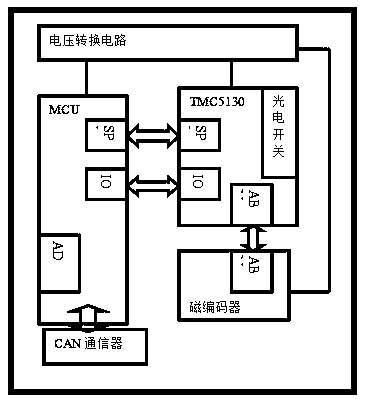
The invention provides a mechanical arm control system. The mechanical arm control system comprises a chip and a microprocessor, wherein the chip comprises a sinusoidal current register and an inverseelectromagnetic potential induction register; the microprocessor conducts communication with the sinusoidal current register and the inverse electromagnetic potential induction register correspondingly; the microprocessor accesses the sinusoidal current register to regulate the output current so as to enable the output current to be matched with torque of a mechanical arm; the microprocessor further accesses the inverse electromagnetic potential induction register and is used for setting the rotating speed and the inverse electromagnetic potential level of torque so as to control the currentof the mechanical arm when the torque load reaches up to the actual limit and the current of the mechanical arm maintaining the posture.

Description

technical field [0001] The present invention relates to the field of robots, in particular to a control system of a mechanical arm and the mechanical arm. Background technique [0002] At present, the battery capacity of mobile robots is limited, and the current of the mechanical arm that moves frequently is huge, which seriously affects the service time and life of the robot. In order to deal with the power consumption problem, existing technical solutions are achieved by increasing the battery volume or reducing the degree of freedom (number of axes) of the robotic arm or reducing the power. However, the increase in battery size is prone to overheating the fuselage, increasing the difficulty of after-sales installation and replacement, and also prone to safety hazards during use. Reduce the degree of freedom of the robotic arm, many postures cannot be formed and maintained, and have no practical value. Reducing the power reduces the application places. That is, the prio...

Claims


Application Information

Patent Timeline
Patent Type & Authority Applications(China)
IPC IPC(8): B25J9/16
CPCB25J9/1602
Inventor 寇宇张弛
Owner ZHEJIANG ZHILING ROBOT TECH CO LTD
Learn More