Reversing machine and reversing method thereof

A technology of reversing machines and reversing rollers, which is applied in the direction of conveyors, conveyor objects, transportation and packaging, etc., which can solve problems such as jamming, inclination of butt joint rollers, and heavy mass of sterilization trays, etc., to achieve increased stability Sexuality, cost reduction, and the effect of shortening the itinerary

Active Publication Date: 2019-08-23
TRUKING TECH LTD
View PDF10 Cites 4 Cited by
  • Summary
  • Abstract
  • Description
  • Claims
  • Application Information

AI Technical Summary

Problems solved by technology

[0003] Due to the heavy weight of the fully loaded sterilization tray, when it is initially transported to the docking roller table, the docking roller table is only partially stressed. This force presses the jacking cylinder from top to bottom, and the gas in the jacking cylinder will be compressed, resulting in the butt joint. The roller table has a certain inclination, which makes it difficult for the fully loaded sterilization tray to enter the docking roller table smoothly, or even get stuck

Method used


Image

  • Reversing machine and reversing method thereof
  • Reversing machine and reversing method thereof
  • Reversing machine and reversing method thereof

Examples


Embodiment 1

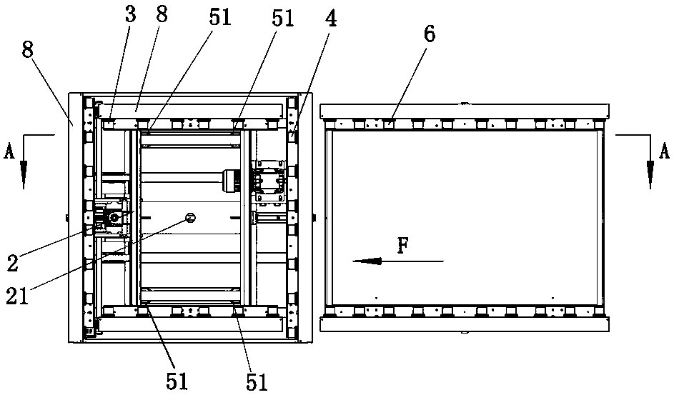
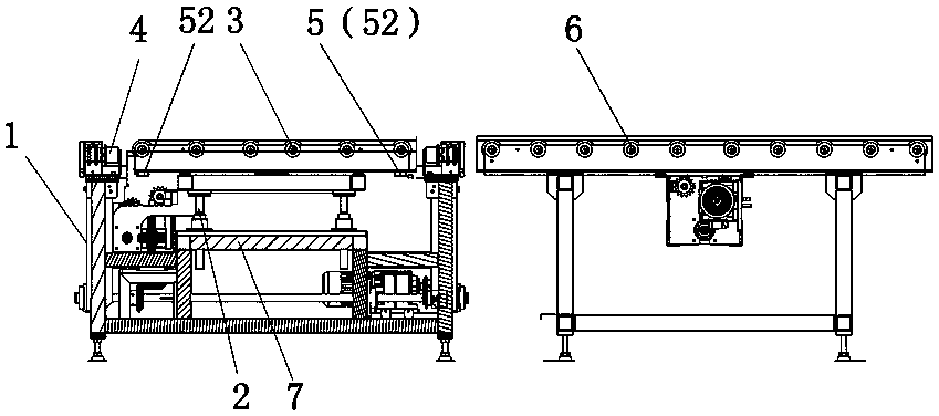
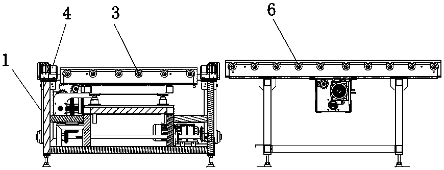
[0029] Figure 1 to Figure 3 An embodiment of the reversing machine of the present invention is shown. The reversing machine of this embodiment includes a frame 1, a jacking mechanism 2, a transition track 3 and a reversing track 4 vertically docked with the transition track 3, and the reversing The track 4 is arranged on the frame 1, the transition track 3 is located on the upper side of the jacking mechanism 2 and is connected with the jacking mechanism 2, the frame 1 is provided with a base 7 and a movable supporting device 5 for supporting the transition track 3, The jacking mechanism 2 is installed on the base 7 .

[0030] The reversing machine is equipped with a movable support device 5 on the frame 1. When the material to be reversed (such as a fully loaded sterilization tray) is transferred to the transition track 3, the movable support device 5 can be used to provide stability for the transition track 3 in advance. The support to complete the reliable positioning of ...

Embodiment 2

[0037] Such as Figure 4 As shown, the commutation method of the present embodiment commutator comprises the following steps:

[0038] S1. The rigid support block 52 protrudes to provide support for the transition rail 3: the jacking cylinder 21 drives the transition rail 3 to rise, and then each telescopic cylinder drives each rigid support block 52 to extend below the transition rail 3, and finally the jacking cylinder 21 drives the transition The track 3 is lowered onto each rigid support block 52; through this step, the rigid support block 52 provides reliable support for the transition track 3 in advance, avoiding the subsequent inclination of the material to be reversed when it enters the transition track 3, and ensuring that the material to be reversed can be stable. , smoothly transported to the transition rail 3; the transition rail 3 needs to be at the same height as the upstream conveying rail 6 after descending to each rigid support block 52, which is conducive to ...


PUM


Abstract

The invention discloses a reversing machine. The reversing machine comprises a machine frame, a jacking mechanism, a transition rail and a reversing rail in perpendicular butt joint with the transition rail, the reversing rail is arranged on the machine frame, the transition rail is located on the upper side of the jacking mechanism and is connected with the jacking mechanism, a base and a movablesupporting device used for supporting the transition rail are arranged on the machine frame, and the jacking mechanism is arranged on the base. The invention further discloses a reversing method of the reversing machine. The reversing method of the reversing machine comprises the following steps that S1, the movable supporting device extends out to support the transition rail; S2, a to-be-reversed material is transferred to the transition rail; S3, the movable supporting device retracts to provide a descending space for the transition rail; S4, the to-be-reversed material is transferred to the reversing rail; S5, reversing is completed, wherein the reversing rail operates to convey the to-be-reversed material towards the downstream portion. The reversing machine and the reversing method thereof have the advantage that reversing is smooth and stable and the like.

Description

technical field [0001] The invention relates to logistics conveying equipment and a conveying method thereof, and specifically discloses a reversing machine and a reversing method thereof. Background technique [0002] Taking the sterilization logistics transportation system as an example, due to the layout of the production line, it is often necessary to realize the vertical transportation of the sterilization tray and keep the orientation of the sterilization tray itself unchanged, which is usually realized by a lifting component lifted by a cylinder. When the sterilizing tray is transported from the upstream conveying roller table to the reversing machine, the cylinder jacks up to drive the docking roller table to rise and connect with the upstream conveying roller table, and then the docking roller table starts to run, and the sterilizing disk is transferred from the upstream conveying roller table to the docking roller table , then the butt roller table stops running, a...

Claims


Application Information

Patent Timeline
IPC IPC(8): B65G47/57B65G47/24
CPCB65G47/24B65G47/57B65G2201/0267
Inventor 贺辅宁
Owner TRUKING TECH LTD
Why Eureka
Try Eureka