Concrete and masonry structure butting portion automatic net hanging device and method

A masonry structure and concrete technology, which is applied in building structure, covering/lining, construction, etc., can solve problems such as weak sense of responsibility of construction personnel, increased difficulty of decoration works, and lack of anti-cracking effect, reaching the scope of application Wide, prevent cement solidification, easy to operate

Active Publication Date: 2019-08-23
CHINA THIRD METALLURGICAL GRP
View PDF5 Cites 13 Cited by
  • Summary
  • Abstract
  • Description
  • Claims
  • Application Information

AI Technical Summary

Problems solved by technology

[0002] In order to prevent cracks in the plastering layer due to the different expansion coefficients of different material bases, anti-crack reinforcement materials should be laid on the surface of the junction of different material bases. At present, manual hanging nets are usually used before plastering construction. During the construction process, due to the poor sense of responsibility of the construction personnel, there are often problems of missing hanging or non-standard glue after hanging the net, which cannot achieve the proper anti-cracking effect, resulting in cracks after the construction of the plastering project. The decoration works increase the difficulty

Method used


Image

  • Concrete and masonry structure butting portion automatic net hanging device and method
  • Concrete and masonry structure butting portion automatic net hanging device and method
  • Concrete and masonry structure butting portion automatic net hanging device and method

Examples


Embodiment Construction

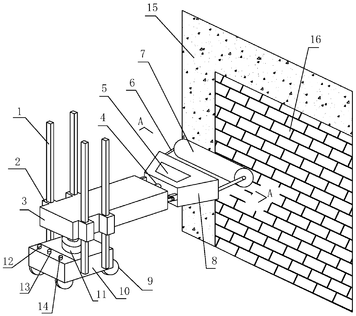
[0028] The specific embodiment of the present invention will be further described below in conjunction with accompanying drawing:

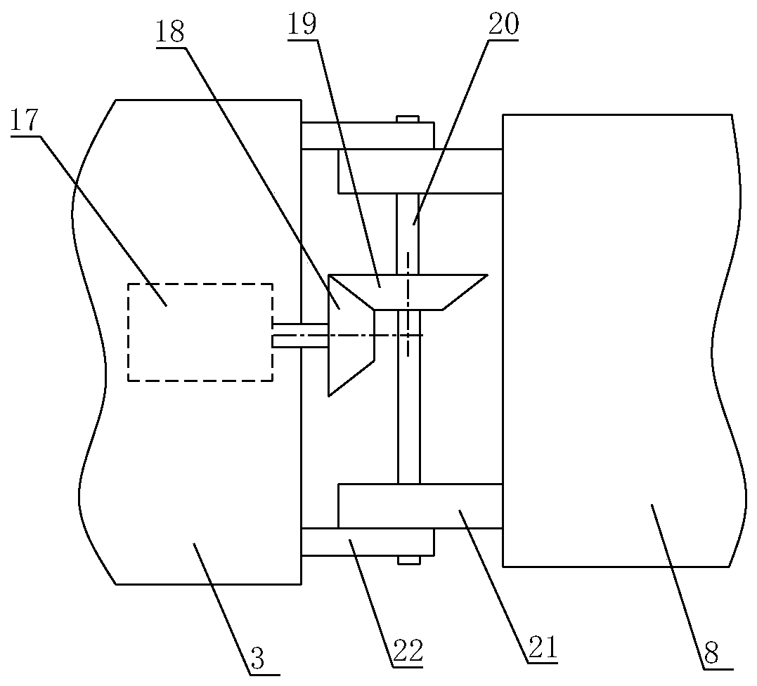
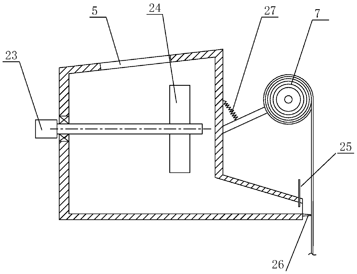
[0029] Such as figure 1 As shown, an automatic net hanging device for the stubble joint of concrete and masonry structure according to the present invention includes a mobile trolley, a lifting device 11, a cantilever 3, a machine head rotating device 4, a cement mixing extrusion box 8 and a glass fiber net laying frame The cantilever 3 is installed on the mobile trolley through the lifting device 11, and can be vertically lifted with the lifting device 11; the cement mixing and extruding box 8 is arranged at one end of the cantilever 3, and the mixing and extruding box 8 and the cantilever 3 are hinged structure and is connected by the head rotating device 44; the top of the cement mixing extrusion box 8 is provided with a cement inlet 5, the inside is provided with a stirring device, the bottom of the outer end is provided with a cement outlet,...


PUM


Abstract

The invention relates to a concrete and masonry structure butting portion automatic net hanging device and a concrete and masonry structure butting portion automatic net hanging method. The concrete and masonry structure butting portion automatic net hanging device comprises a moving trolley, a lifting device, a cantilever, a machine head rotation device, a gum and cement mixed extrusion box and aglass fiber net laying frame, wherein the cantilever is installed on the moving trolley through the lifting device, the gum and cement mixed extrusion box is arranged at one end of the cantilever, ahinge structure is arranged between the gum and cement mixed extrusion box and the cantilever, the gum and cement mixed extrusion box and the cantilever are connected through the machine head rotationdevice, a gum and cement feeding port is formed in the top of the gum and cement mixed extrusion box, a stirring device is arranged in the gum and cement mixed extrusion box, a gum and cement outletis formed in the bottom of the outer end of the gum and cement mixed extrusion box, a gum and cement scraper blade is arranged on the gum and cement outlet, a glass fiber net laying frame is arrangedabove the gum and cement outlet, and under the action of the machine head rotation device, a machine head composed of the gum and cement mixed extrusion box and the glass fiber net laying frame can overall rotate between the horizontal direction and the vertical direction. The concrete and masonry structure butting portion automatic net hanging device can complete the laying and gumming process ofa glass fiber gridding cloth in one time, is high in construction quality and high in efficiency, and greatly reduces labor intensity of constructors.

Description

technical field [0001] The invention relates to the technical field of building construction, in particular to an automatic net-hanging device and method for stubble joints between concrete and masonry structures. Background technique [0002] In order to prevent cracks in the plastering layer due to the different expansion coefficients of different material bases, anti-crack reinforcement materials should be laid on the surface of the junction of different material bases. At present, manual hanging nets are usually used before plastering construction. During the construction process, due to the poor sense of responsibility of the construction personnel, there are often problems of missing hanging or non-standard glue after hanging the net, which cannot achieve the proper anti-cracking effect, resulting in cracks after the construction of the plastering project. The decoration works added difficulty. Contents of the invention [0003] The invention provides an automatic n...

Claims


Application Information

Patent Timeline
Patent Type & Authority Applications(China)
IPC IPC(8): E04F21/00E04F13/076
CPCE04F13/0885E04F13/0889E04F21/00
Inventor 任涛刘剑丰王巍李波赵晓姣刘操张焕哲
Owner CHINA THIRD METALLURGICAL GRP
Why Eureka
Try Eureka