
Automatic pull-up device for oil well pipeline

A technology for pipelines and oil wells, which is applied in the field of automatic pulling devices for oil well pipelines, which can solve problems such as laborious pulling up, high friction, and insufficient clamping stability, and achieve the effects of great flexibility, reduced friction, and convenient operation

Active Publication Date: 2019-08-23
延安中诚商务有限公司
View PDF7 Cites 2 Cited by
  • Summary
  • Abstract
  • Description
  • Claims
  • Application Information

AI Technical Summary

Problems solved by technology

[0002] The oil well pipe is a pipe installed underground. It is used to guide the oil when oil is extracted. The oil pipe is driven into the ground through the pile driver equipment. When the oil in a place is exhausted, the corresponding pipe needs to be pulled out. , and then replace the mining position, the oil well pipe is relatively long, and the friction with the ground is relatively large, and it is very laborious to pull it out. At present, there is a pipe puller, such as the patent No. CN201610166051.0 provides a "a drill pipe puller The device is composed of beam frame, clamping tiles, etc. The advantage is that it is small in size and can be installed on site. The disadvantage is that the pipe is directly pulled up abruptly, with high resistance, low efficiency, and unstable clamping.

Method used


Image

  • Automatic pull-up device for oil well pipeline
  • Automatic pull-up device for oil well pipeline
  • Automatic pull-up device for oil well pipeline

Examples


Embodiment

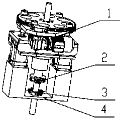
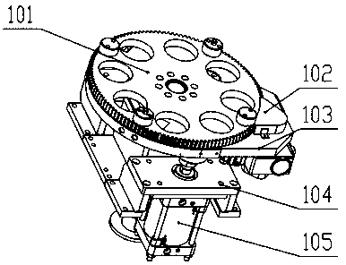
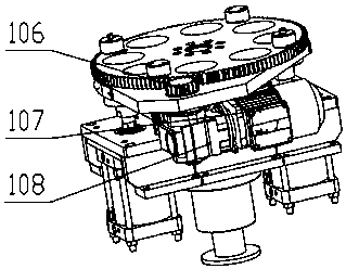
[0039] Such as figure 1 As shown, an oil well pipeline automatic pulling device includes a lifting device 1, a first clamping mechanism 2, a second clamping mechanism 3 and a base 4;

[0040] The base 4 is fixedly installed with a lifting device 1 capable of rotating and lifting upwards;

[0041] The lower end of the lifting device 1 is fixedly installed with a first clamping mechanism 2;

[0042] A second clamping mechanism 3 is fixedly installed on the base 4;

[0043] The second clamping mechanism 3 is located at the lower end of the first clamping mechanism 2 and is aligned with the axis of the first clamping mechanism 2;

[0044] When lifting the oil well pipeline, first the first clamping mechanism 2 clamps the oil well pipeline, at this time the second clamping mechanism 3 is in a loose state, and then the lifting device 1 lifts up the oil well pipeline while rotating with the first clamping mechanism 2, When the lifting device 1 is lifted to the limit position, the ...


PUM


Abstract

The invention provides an automatic pull-up device for an oil well pipeline. The automatic pull-up device comprises a lifting device, a first clamping mechanism and a second clamping mechanism, and the lifting device is fixedly installed on a base; the first clamping mechanism is fixedly installed at the lower end of the lifting device, and the second clamping mechanism is fixedly installed on thebase, located at the lower end of the first clamping mechanism, and aligned to the axis of the first clamping mechanism; and an oil pipeline is pulled out through the lifting device, the first clamping mechanism and the second clamping mechanism automatically. According to the automatic pull-up device, rotation and upward lifting action can be achieved through the lifting device, and pull-out ofthe oil well pipeline from the ground is benefited; and the clamping mechanisms of the automatic pull-up device are provided with pulleys so that friction with the surface of the oil well pipeline isreduced, and friction with the oil well pipeline can be increased through arrangement of a rubber plate.

Description

technical field [0001] The invention relates to the technical field of oil exploitation industrial equipment, in particular to an automatic pulling device for oil well pipelines. Background technique [0002] The oil well pipe is a pipe installed underground. It is used to guide the oil when oil is extracted. The oil pipe is driven into the ground through the pile driver equipment. When the oil in a place is exhausted, the corresponding pipe needs to be pulled out. , and then replace the mining position, the oil well pipe is relatively long, and the friction with the ground is relatively large, and it is very laborious to pull it out. At present, there is a pipe puller, such as the patent No. CN201610166051.0 provides a "a drill pipe puller The device is composed of beam frame, clamping tiles, etc. The advantage is that it is small in size and can be installed on site. The disadvantage is that the pipe is directly pulled up abruptly, with high resistance, low efficiency, and...

Claims


Application Information

Patent Timeline
Patent Type & Authority Applications(China)
IPC IPC(8): E21B23/00
CPCE21B23/00
Inventor 王俊香
Owner 延安中诚商务有限公司
Learn More