
Rotating equipment state monitoring method and device

A technology of rotating equipment and state, which is applied in measuring devices, testing of machines/structural components, and measuring ultrasonic/sonic/infrasonic waves. performance, real-time monitoring, and risk avoidance

Inactive Publication Date: 2019-08-23
湃方科技(北京)有限责任公司
View PDF12 Cites 3 Cited by
  • Summary
  • Abstract
  • Description
  • Claims
  • Application Information

AI Technical Summary

Problems solved by technology

[0004] However, in the monitoring method in the prior art, the piezoelectric sensor used is bulky, the power supply voltage is high, the battery power supply is inconvenient, and the low frequency response performance is poor
Data analysis and determination of operating status need to be judged based on workers' experience, which is highly subjective and the judgment results are inaccurate, so it is not suitable for mass promotion

Method used


Image

  • Rotating equipment state monitoring method and device
  • Rotating equipment state monitoring method and device
  • Rotating equipment state monitoring method and device

Examples


Embodiment Construction

[0031] In order to make the purpose, technical solutions and advantages of the embodiments of the present invention clearer, the technical solutions in the embodiments of the present invention will be clearly and completely described below in conjunction with the drawings in the embodiments of the present invention. Obviously, the described embodiments It is a part of embodiments of the present invention, but not all embodiments. Based on the embodiments of the present invention, all other embodiments obtained by persons of ordinary skill in the art without making creative efforts fall within the protection scope of the present invention.

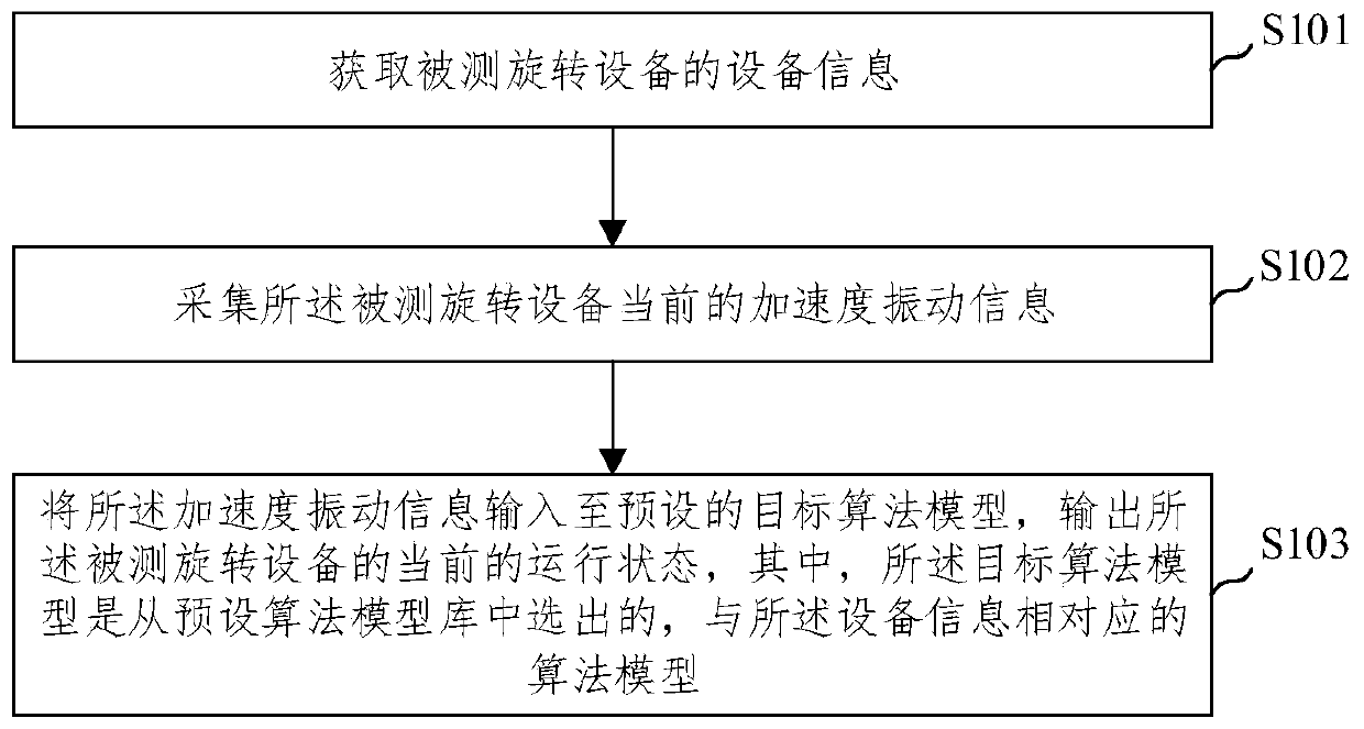
[0032] figure 1 A schematic diagram of a method for monitoring the condition of rotating equipment provided by an embodiment of the present invention, as shown in figure 1 As shown, the embodiment of the present invention provides a method for monitoring the state of rotating equipment, the execution body of which is a device for monitorin...


PUM


Abstract

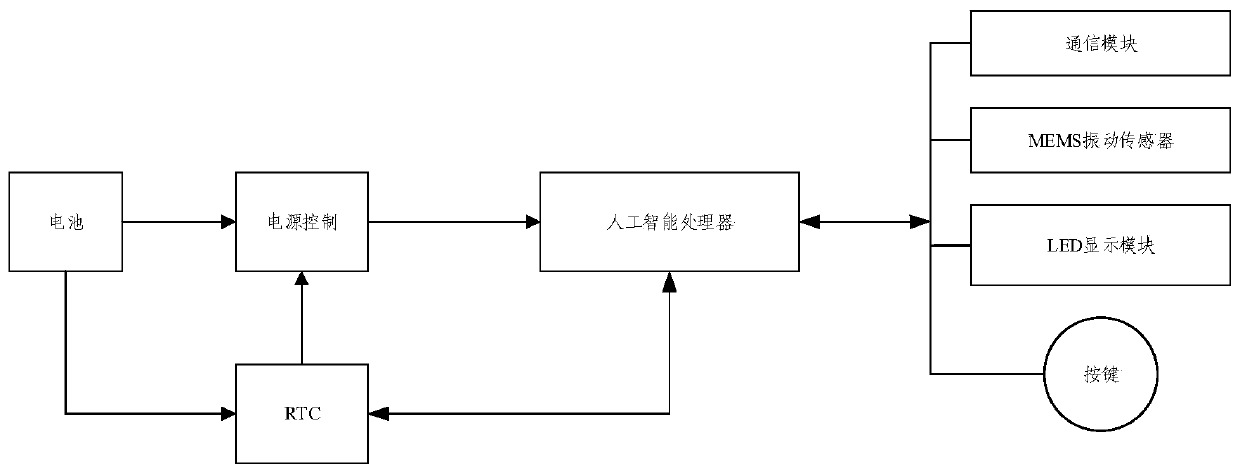
The embodiment of the invention provides a rotating equipment state monitoring method and device. The method comprises the following steps: acquiring equipment information of monitored rotating equipment; collecting the current acceleration vibration information of the monitored rotating equipment; inputting the acceleration vibration information into a preset target algorithm model, and outputting the current running state of the monitored rotating equipment, wherein the target algorithm model is selected from a preset algorithm model library, and is the algorithm model corresponding to the equipment information. Through the rotating equipment state monitoring method and device provided by the embodiment of the invention, the acceleration vibration information collected by a MEMS vibration sensor can be processed in real time by adopting an artificial intelligent processor, thereby obtaining the current running state of the monitored rotating equipment, the real-time monitoring of therotating equipment can be realized, the result inaccuracy caused by artificial analysis is eliminated, and the possible risk is avoided.

Description

technical field [0001] The invention relates to the technical field of automatic control, in particular to a method and device for monitoring the state of rotating mechanical equipment. Background technique [0002] Rotating mechanical equipment is referred to as rotating equipment. Rotating equipment is more and more widely used in daily life and production. It is very important to monitor the operating status of rotating equipment and understand the operating status of rotating equipment in real time. [0003] In the prior art, two sets of three-dimensional (X, Y, Z directions) acceleration vibration sensors are installed on the shaft seats at both ends of the rotating equipment to measure the vibration displacement vector, and the main shaft and the bearing bush (shaft seat) are monitored for the monitoring of the state of the rotating equipment. The vibration sensor uses the positive piezoelectric effect of the piezoelectric crystal. When the piezoelectric crystal is und...

Claims


Application Information

Patent Timeline
Patent Type & Authority Applications(China)
IPC IPC(8): G01M99/00G01H17/00
CPCG01H17/00G01M99/005
Inventor 杜志科李华来李金阳李文彬张殿睿武通达刘勇攀
Owner 湃方科技(北京)有限责任公司
Learn More