
Osmotic pressure device and testing method used for high-pressure solid bentonite test

A technology of bentonite and high-pressure compaction, which is applied in the direction of measuring devices, applying stable tension/pressure to test material strength, and preparation of test samples, which can solve the problem of poor data representation of expansion force data collection points and difficulty in completely saturating soil , the test results are greatly affected, etc., to achieve the effect of avoiding uneven hydration and good anisotropy characteristics

Active Publication Date: 2019-08-23
TONGJI UNIV
View PDF6 Cites 4 Cited by
  • Summary
  • Abstract
  • Description
  • Claims
  • Application Information

AI Technical Summary

Problems solved by technology

However, both types of test devices have certain limitations
For the cube-shaped sample test device, when the sample size is too large, it is difficult to fully saturate the soil; if the size is too small, the device will have a greater impact on the test results, and the size effect will be obvious
For the circular cake-shaped sample test device, the uneven hydration leads to poor representativeness of the data collection points of the expansion force data in the vertical compaction direction, which cannot reflect the overall expansion of the sample
At the same time, since the two types of test devices are equipped with sensors in the lateral direction, it is not conducive to carry out the permeation anisotropy test.

Method used


Image

  • Osmotic pressure device and testing method used for high-pressure solid bentonite test
  • Osmotic pressure device and testing method used for high-pressure solid bentonite test
  • Osmotic pressure device and testing method used for high-pressure solid bentonite test

Examples


Embodiment

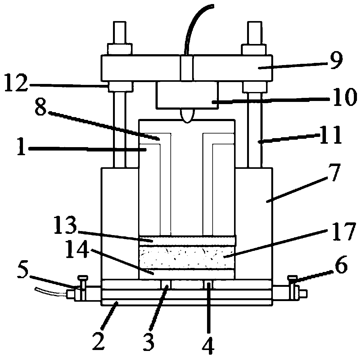
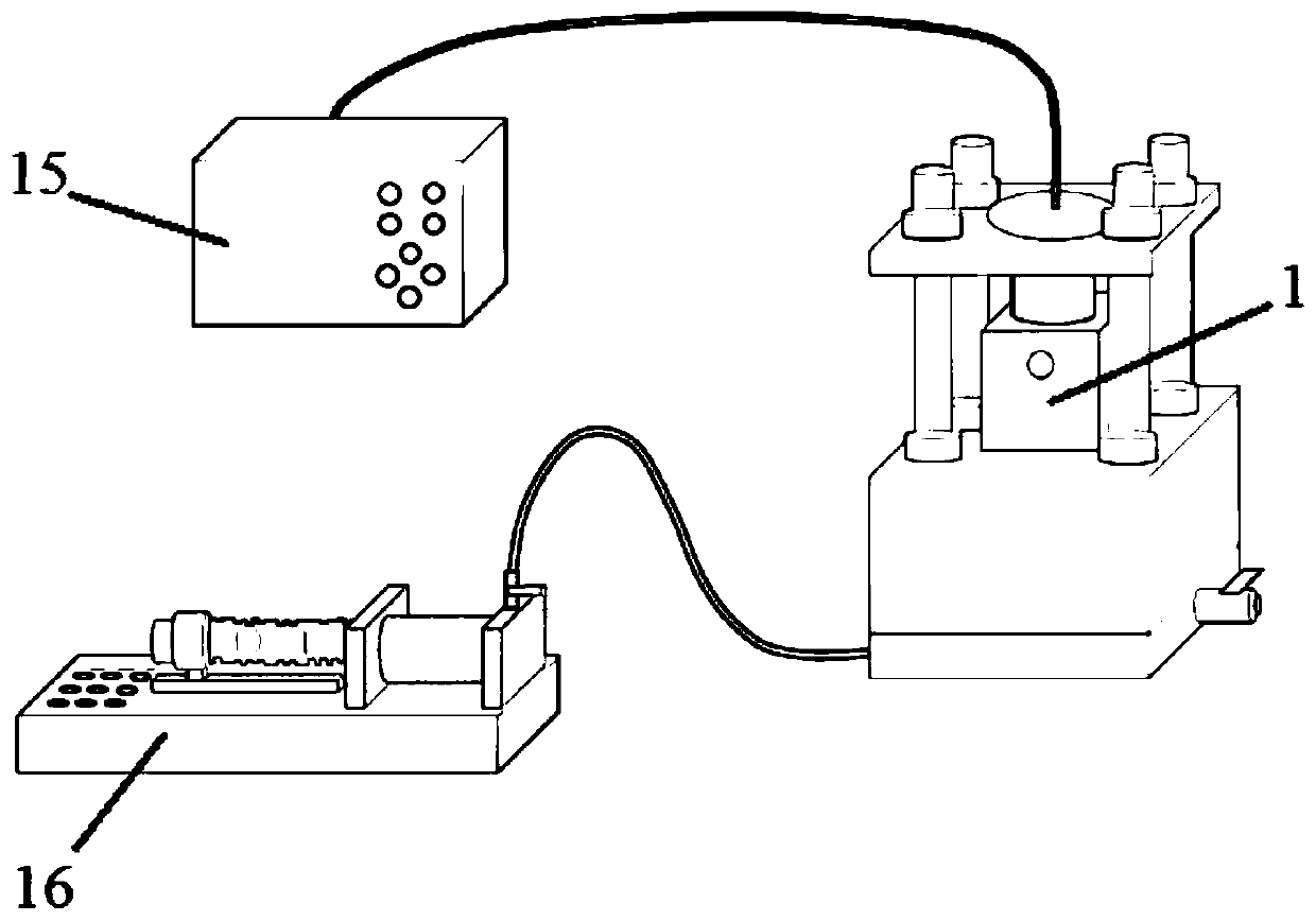
[0028] Such as figure 1 The osmotic pressure device used for the high-compacted bentonite test is shown, including the bottom water injection and exhaust mechanism, the side closure mechanism arranged on the bottom water injection and exhaust mechanism, and the side closure mechanism inserted in the side closure mechanism and sliding with the side closure mechanism The connected piston 1, the bottom water injection exhaust mechanism, the side sealing mechanism and the piston 1 form a bentonite test chamber. The bentonite test chamber is square, and the height of the bentonite test chamber is smaller than the width.

[0029] Wherein, the bottom water injection and exhaust mechanism includes a base plate 2 and a base plate water injection channel and a base plate exhaust channel respectively opened in the base plate 2. The base plate 2 is provided with a base plate water injection hole 3 connected with the base plate water injection channel and connected with the base plate exhau...


PUM


Abstract

The invention relates to an osmotic pressure device and a testing method for a high-pressure solid bentonite test. The osmotic pressure device comprises a bottom water injection and exhaust mechanism,a side surface sealing mechanism and a piston, wherein the side surface sealing mechanism is arranged on the bottom water injection and exhaust mechanism, and the piston is inserted into the side surface sealing mechanism and is in sliding connection with the side surface sealing mechanism; the bottom water injection and exhaust mechanism, the side surface sealing mechanism and the piston definea bentonite test cavity, wherein the bentonite test cavity is square, and the height of the bentonite test cavity is smaller than the width; in a test, a bentonite sample parallel to the compaction direction and a bentonite sample perpendicular to the compaction direction are placed in the bentonite test cavity for testing. Compared with the prior art, the method has the advantages that the thickness in the direction of measuring the expansion force and the permeability coefficient direction of the bentonite sample can be reduced, the influence of non-uniform swelling of bentonite is avoided,and the device is suitable for measuring the expansion force and the permeability coefficient of the high-pressure solid bentonite in parallel to the compaction direction and perpendicular to the compaction direction.

Description

technical field [0001] The invention belongs to the technical field of geotechnical engineering, and relates to an osmotic pressure device and a test method for measuring the swelling force and osmotic properties of high-compacted bentonite. Background technique [0002] One-way compacted bentonite blocks are often used as buffer backfill materials in high-level radioactive waste geological repositories. In the process of unidirectionally compacting the powdery bentonite in the natural state into a high-compacted soil block with a certain dry density, the soil will produce an anisotropic structure, which will lead to anisotropic expansion and permeability characteristics of the high-compacted soil block. opposite sex. [0003] At present, the devices used to study the expansion and permeability anisotropy of high-compacted bentonite can be divided into two categories according to the geometry of the samples used: cube-shaped samples or circular cake-shaped samples. These t...

Claims


Application Information

Patent Timeline
IPC IPC(8): G01N3/12G01N15/08G01N1/36
CPCG01N1/36G01N3/12G01N15/0826G01N2001/366
Inventor 陈宝毛耀建
Owner TONGJI UNIV
Learn More