
Steel plate straightening mechanism and steel plate straightening method

A technology of steel plate and steel wheel, which is applied in the field of steel plate correction mechanism and steel plate correction, and can solve the problems of low work efficiency of steel plate correction

Active Publication Date: 2021-05-14
CHINA FIRST METALLURGICAL GROUP
View PDF8 Cites 0 Cited by
  • Summary
  • Abstract
  • Description
  • Claims
  • Application Information

AI Technical Summary

Problems solved by technology

[0004] One of the purposes of this application is to provide a steel plate straightening mechanism and a steel plate straightening method, aiming at improving the problem of low working efficiency of steel plate straightening in the prior art

Method used


Image

  • Steel plate straightening mechanism and steel plate straightening method
  • Steel plate straightening mechanism and steel plate straightening method

Examples


Embodiment

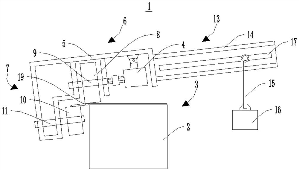
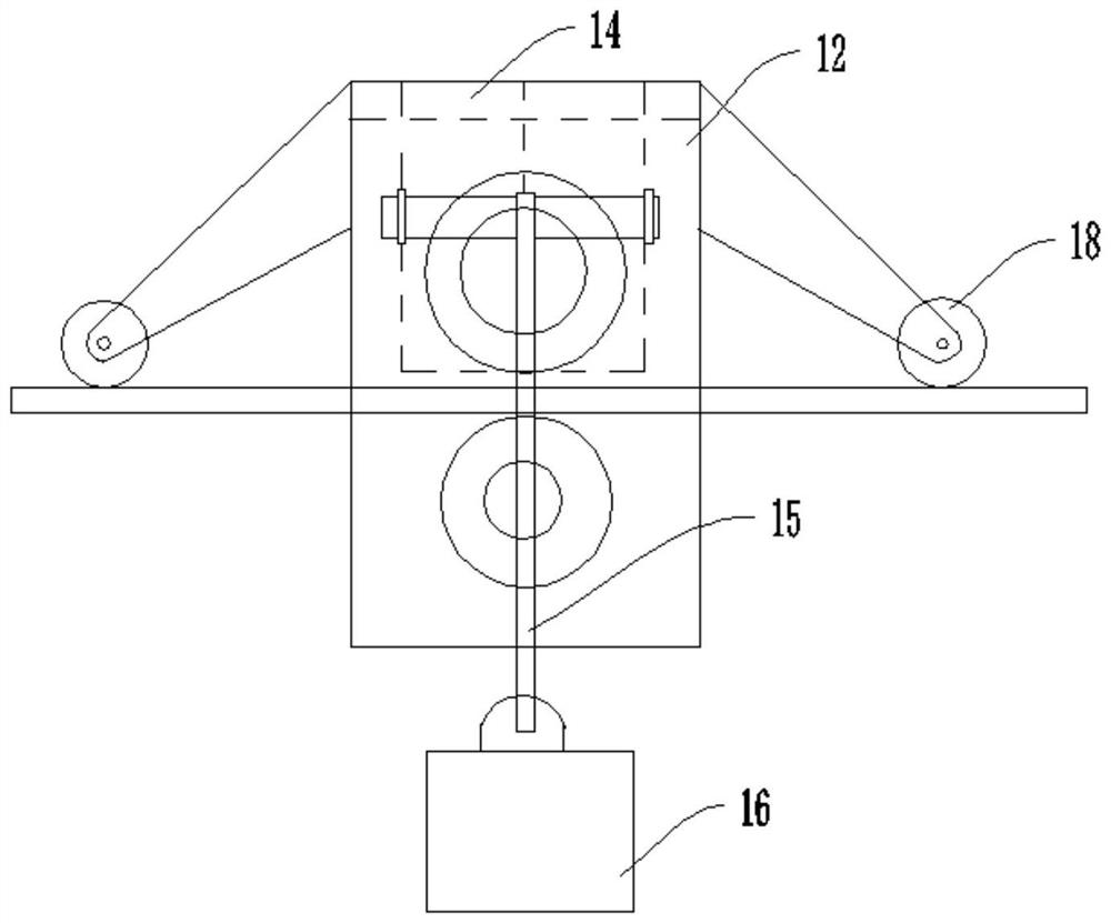
[0049] Please refer to figure 1 , with reference to figure 2 , the present application provides a steel plate correction mechanism 1 for correcting deformed steel plates 19, which includes a support structure 2, a correction assembly 3 and a drive structure 4, wherein the correction assembly 3 is obliquely arranged on the support structure 2, and can be used Rolling on the deformed steel plate 19 ; the driving structure 4 is in transmission connection with the straightening component 3 , and is used to drive the straightening component 3 to roll on the deformed steel plate 19 .

[0050] It should be noted that, in this embodiment, the support structure 2 adopts a steel box girder structure; in other embodiments, the support structure 2 may also adopt other structures according to actual usage conditions.

[0051] It should be noted that, in this embodiment, the drive structure 4 includes a geared motor, which is in transmission connection with the straightening assembly 3 , ...


PUM


Abstract

The application provides a steel plate straightening mechanism and a steel plate straightening method, which belong to the construction field. It includes a support structure; a rectification component, which is obliquely arranged on the support structure and can be used for rolling on the deformed steel plate; a driving structure, which is connected to the rectification component in transmission, and is used to drive the rectification component to roll on the deformed steel plate. The device has a good straightening effect on the deformed steel plate, and can effectively improve the working efficiency of the steel plate straightening.

Description

technical field [0001] The present application relates to the construction field, in particular to a steel plate straightening mechanism and a steel plate straightening method. Background technique [0002] At present, with the emergence of steel materials with high strength, good toughness, good fatigue resistance and corrosion resistance, and the appearance of light and high-strength orthotropic slab bridge decks formed by welding flat steel plates and reinforced with angle steel and plate steel, Steel bridges have made great progress, and steel structure bridges have been used more and more widely. In long-span cable-supported bridges, steel box girders span hundreds of meters to thousands of meters, and are generally manufactured and installed in several beam sections, with wide and flat cross-sections. [0003] In the manufacturing process of steel structure bridge box girder, there are often reasons for weld concentration and excessive heat, which lead to deformation ...

Claims


Application Information

Patent Timeline
Patent Type & Authority Patents(China)
IPC IPC(8): B21D1/02B21D47/01
CPCB21D1/02B21D47/01
Inventor 杨晓建李晓铭古纳所明义
Owner CHINA FIRST METALLURGICAL GROUP
Learn More