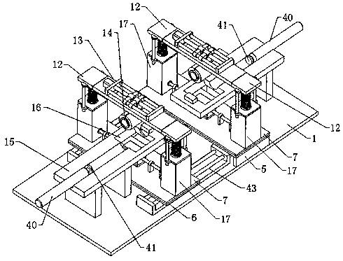
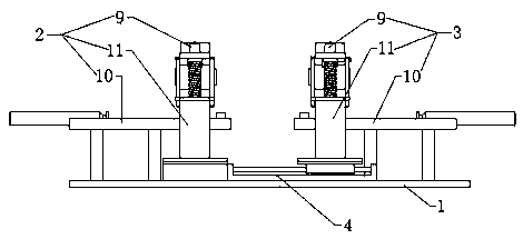
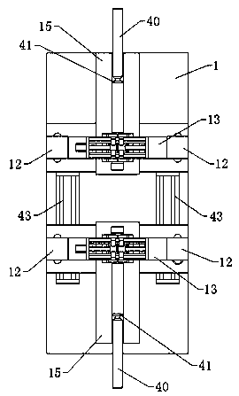
Welding equipment for automobile pipe fitting machining

A technology for welding equipment and pipe fittings, applied in welding equipment, auxiliary welding equipment, metal processing equipment, etc., can solve problems such as unqualified products, affecting welding efficiency, and rework

Active Publication Date: 2019-08-27
极能电气(苏州)有限公司
View PDF13 Cites 12 Cited by
  • Summary
  • Abstract
  • Description
  • Claims
  • Application Information

AI Technical Summary

Problems solved by technology

[0002] With the continuous development of the automobile industry, the types of automobile pipe fittings continue to increase. During the processing of automobile pipe fittings, the pipe fittings need to be welded. When welding traditional automobile pipe fittings, two pipe fittings are usually simply matched and docked. It is easy to cause one of the two pipe fittings to be too high or too low, so that the two pipe fittings cannot be precisely on the same axis. If the two pipe fittings are not on the same axis or one of the pipe fittings has a deviation, the product will be unqualified after welding. In severe cases It will lead to product damage and rework, which will affect the efficiency of welding. Therefore, we propose a welding equipment for automotive pipe fittings to solve the above problems

Method used


Image

  • Welding equipment for automobile pipe fitting machining
  • Welding equipment for automobile pipe fitting machining
  • Welding equipment for automobile pipe fitting machining

Examples


Embodiment Construction

[0025] The technical solutions of the present invention will be further described below in conjunction with the drawings and specific implementations.

[0026] Among them, the drawings are only used for exemplary description, and they are only schematic diagrams rather than physical drawings, and cannot be understood as a limitation of the patent; in order to better illustrate the embodiments of the present invention, some parts of the drawings may be omitted, Enlargement or reduction does not represent the size of the actual product; for those skilled in the art, it is understandable that some well-known structures in the drawings and their descriptions may be omitted.

[0027] The same or similar reference numerals in the drawings of the embodiments of the present invention correspond to the same or similar components; in the description of the present invention, it should be understood that if the terms "upper", "lower", "left", "right" appear , "内", "外", etc. indicate the orien...


PUM


Abstract

The invention relates to the field of welding equipment, in particular to welding equipment for automobile pipe fitting machining. The welding equipment comprises a workbench, and further comprises aleft end positioning mechanism, a right end positioning mechanism and a right end moving mechanism. The left end positioning mechanism and the right end positioning mechanism are symmetrically arranged above the workbench. The left end positioning mechanism is fixedly arranged on a table top of the workbench through a fixing bracket. The right end moving mechanism is positioned below the right endpositioning mechanism. The right end positioning mechanism is arranged on the top of a horizontal bottom plate. The right end positioning mechanism and the left end positioning mechanism respectivelycomprise a base, a synchronous driving assembly, a positioning assembly, a feeding positioning assembly and two lifting assemblies, wherein each lifting assembly is provided with a lifting plate; each positioning assembly comprises a fixing cross plate and two clamps; each feeding positioning assembly comprises a feeding rail; and each feeding rail is provided with avoidance slots for avoiding the movement of the corresponding two clamps. By means of the welding equipment, the height of each welding pipe fitting can be adjusted separately, so that more precise welding of automobile pipe fittings can be realized, and the welding efficiency can be improved.

Description

Technical field [0001] The invention relates to the field of welding equipment, in particular to a welding equipment used for processing automobile pipe fittings. Background technique [0002] With the continuous development of the automobile industry, the types of automobile pipe fittings continue to increase. When automobile pipe fittings are processed, the pipe fittings need to be welded. When welding traditional automobile pipe fittings, generally two pipe fittings are simply matched and connected. It is easy to cause one of the two pipe fittings to be high or low, so that the two pipe fittings cannot be accurately positioned on the same axis. If the two pipe fittings are not on the same axis or one of the pipe fittings is deviated, the product will be unqualified after the welding machine. It will cause product damage and rework, which will affect the efficiency of welding. Therefore, we have proposed a welding equipment for automotive pipe fittings to solve the above-mentio...

Claims


Application Information

Patent Timeline
Patent Type & Authority Applications(China)
IPC IPC(8): B23K37/053B23K37/00
CPCB23K37/00B23K37/0533
Inventor 佘娟何一峰
Owner 极能电气(苏州)有限公司
Why Eureka
Try Eureka