
Optocoupler detector

An optocoupler detection and optocoupler technology, applied in the field of rail transit, can solve the problems of a large number of brake resistor control boards repaired, low detection efficiency, complicated operation, etc., and achieve the effects of saving manpower, improving efficiency, and improving detection efficiency.

Pending Publication Date: 2019-08-27
HUNAN LIANCHENG TRACK EQUIP CO LTD
View PDF0 Cites 0 Cited by
  • Summary
  • Abstract
  • Description
  • Claims
  • Application Information

AI Technical Summary

Problems solved by technology

[0003] At present, multimeters are generally used to detect the quality of optocouplers, but this method has complex operations, low detection efficiency, and easy false detection
[0004] In the actual production process, when the optocoupler components detected by ordinary methods are installed in the braking resistor control boxes of subway vehicles, the failure rate of the braking resistor control boxes is 30%-50% due to the optocoupler components, making the manufacturing A large number of repairs are required for the debugging of the dynamic resistance control board

Method used


Image

  • Optocoupler detector

Examples


Embodiment 1

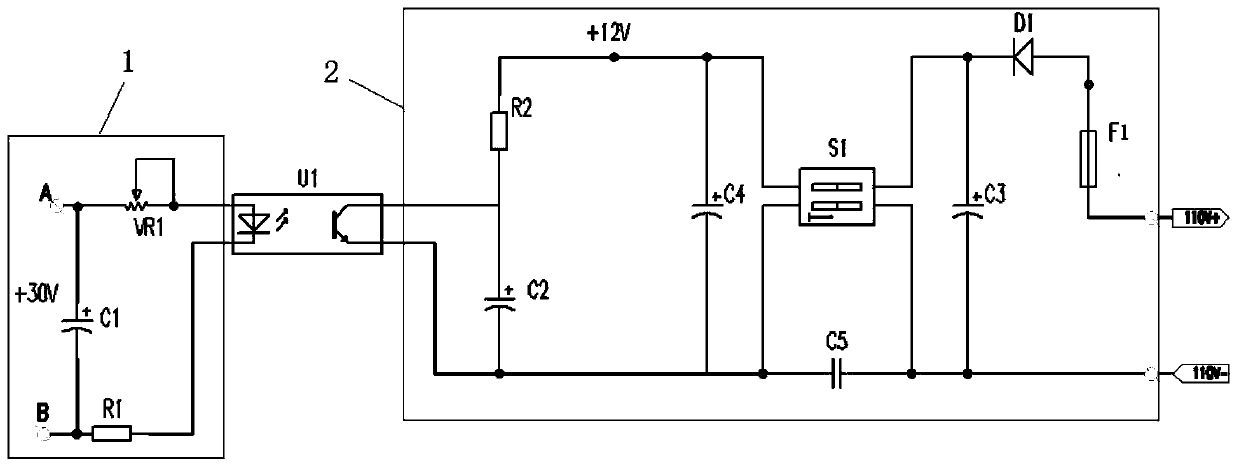
[0031] see figure 1 , an optocoupler detection device, specifically an optocoupler element detection device for a subway vehicle braking resistor control box, including an input voltage adjustment circuit 1, an output circuit 2, and an optocoupler U1, the input voltage adjustment circuit 1 connected to the input end of the optocoupler U1, and the output circuit 2 is connected to the output end of the optocoupler U1;

[0032] The input voltage regulation circuit 1 includes a first power supply, an adjustable potentiometer VR1 and a current limiting resistor R1, the positive pole of the first power supply is connected to the positive pole of the input terminal of the optocoupler U1 through the adjustable potentiometer VR1, and the positive pole of the first power supply The negative pole is connected to the negative pole of the input terminal of optocoupler U1 through the current-limiting resistor R1, and the current in the input voltage regulation loop 1 is adjusted through the...


PUM


Abstract

The invention provides an optocoupler detector, which comprises an input voltage regulation loop, an output loop and an optocoupler, wherein the input voltage regulation loop is connected to the inputend of the optocoupler, and the output loop is connected to the output end of the optocoupler; the input voltage regulation loop comprises a first power supply, an adjustable potentiometer and a current-limiting resistor; a positive electrode of the first power supply is connected to a positive electrode of the input end of the optocoupler through the adjustable potentiometer; a negative electrode of the first power supply is connected to a negative electrode of the input end of the optocoupler through the current-limiting resistor; the magnitude of the current in the input voltage regulationloop is adjusted through the adjustable potentiometer, so that the luminous intensity of a light-emitting diode in the optocoupler is changed, and thus the voltage of the output end of the optocoupler is adjusted, and whether the optocoupler is qualified or not is judged according to the voltage of the output end of the optocoupler. The problems existing in detection through a universal meter inthe prior art are solved, the detection accuracy rate of an optocoupler element by using the optocoupler detector reaches 100%, and meanwhile, the detection efficiency is greatly improved, and the labor and the detection time cost are saved.

Description

technical field [0001] The invention relates to the technical field of rail transit, in particular to an optocoupler detection device, in particular to an optocoupler element detection device for a metro vehicle braking resistor control box. Background technique [0002] Optocoupler is also called opto-isolator or opto-coupler, referred to as opto-coupler. It is a device that uses light as a medium to transmit electrical signals. Usually, the emitter (infrared light-emitting diode LED) and the light receiver (photosensitive semiconductor tube, photoresistor) are packaged in the same package. When the input terminal is powered on, the light emitter emits light, and the light receiver generates photocurrent after receiving the light, which flows out from the output terminal, thus realizing the "electricity-optical-electricity" conversion. [0003] At present, a multimeter is generally used to detect whether the optocoupler is good or bad, but this method has complex operation...

Claims


Application Information

Patent Timeline
Patent Type & Authority Applications(China)
IPC IPC(8): G01R31/00
CPCG01R31/008
Inventor 吴晓喜肖峰阮志新
Owner HUNAN LIANCHENG TRACK EQUIP CO LTD
Learn More