A kind of color-changing OLED device and preparation method thereof
A device and intermediate layer technology, applied in the field of color-changing OLED devices, can solve the problems of short device life, reduction and poor stability, and achieve the effects of good device stability, high brightness and variable color.
- Summary
- Abstract
- Description
- Claims
- Application Information
AI Technical Summary
Problems solved by technology
Method used
Image
Examples
preparation example Construction
[0043] A method for preparing a color-changing OLED device, comprising the following steps:
[0044] Step 1, cleaning and drying the ITO glass 1;
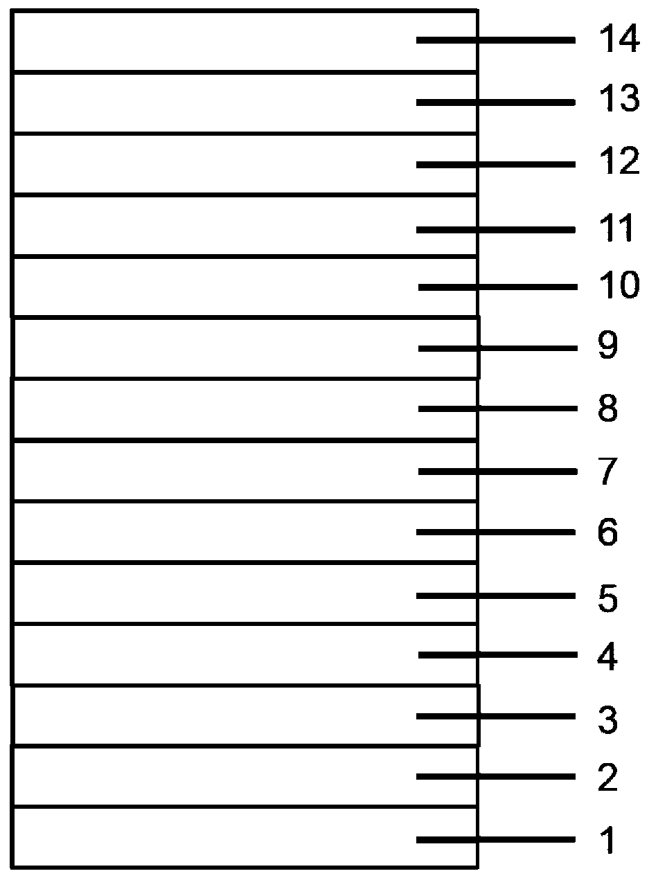
[0045] Step 2, move the ITO glass 1 into the vacuum coating chamber, and sequentially evaporate the first hole injection layer 2, the first hole transport layer 3, the first light-emitting layer 4, and the first electron transport layer 5 on the ITO glass 1 , the first electron injection layer 6, the electron type intermediate layer 7, the hole type intermediate layer 8, the second hole injection layer 9, the second hole transport layer 10, the second light emitting layer 11, the second electron transport layer 13, The second electron injection layer and the cathode electrode 14 form an organic electroluminescent device;
[0046] In step 3, the device prepared in step 2 is packaged in a glove box, and the glove box is a nitrogen atmosphere.
[0047] During the test, the current-voltage-brightness characteristic curve of the devic...
Embodiment 1
[0051] like figure 1 As shown, the first hole injection layer 2 and the second hole injection layer 9 in the device structure are MoO3 (molybdenum trioxide), and the first hole transport layer 3 and the second hole transport layer 10 are NPB (C44H32N2) , the host material of the first light emitting layer 4 is CBP (C36H24N2), the guest dye is Ir(piq)2(acac)(C35H27N2O2Ir), the first electron transport layer 5 and the second electron transport layer 13 are Bphen(4,7- Biphenyl-1,10-phenanthroline, the first electron injection layer 6 and the second electron injection layer are LiF (lithium fluoride), the electron type intermediate layer 7 is C60 (fullerene), the hole type intermediate layer Layer 8 is CuPc (copper phthalocyanine), the host material of the second light-emitting layer 11 is CBP (C36H24N2), and the guest dye is FIrpic (bis(4,6-difluorophenylpyridine-N,C2) pyridineformyl iridium ), the cathode electrode 14 is aluminum. The whole device structure is described as:
...
Embodiment 2
[0061] like figure 1 As shown, the host material of the first light-emitting layer 44 in the device structure is CBP (C36H24N2), and the guest dye is FIrpic (bis (4,6-difluorophenylpyridine-N, C2) picolinate iridium), the first The host material of the second light-emitting layer 1111 is CBP (C36H24N2), and the guest dye is Ir(piq)2(acac)(C35H27N2O2Ir). The entire device structure is described as:
[0062] Glass substrate / ITO / MoO3(3nm) / NPB(30nm) / CBP:10%FIrpic(30nm) / BPhen(40nm) / LiF(1nm) / C60(5nm) / CuPc(5nm) / MoO3(3nm) / NPB(30nm) / CBP:5%Ir(piq)2(acac)(30nm) / BPhen(40nm) / LiF(1nm) / Al(150nm)
[0063] The fabrication process of the device is similar to that of Example 1.
[0064] Device B was produced in Example 2.
PUM
 Abstract
Description
Claims
Application Information
 - R&D
- Intellectual Property
- Life Sciences
- Materials
- Tech Scout
- Unparalleled Data Quality
- Higher Quality Content
- 60% Fewer Hallucinations
Browse by: Latest US Patents, China's latest patents, Technical Efficacy Thesaurus, Application Domain, Technology Topic, Popular Technical Reports.
© 2025 PatSnap. All rights reserved.Legal|Privacy policy|Modern Slavery Act Transparency Statement|Sitemap|About US| Contact US: help@patsnap.com


