Heat source-side unit and refrigeration cycle device

A heat source side, refrigerant technology, used in refrigerators, refrigeration components, refrigeration and liquefaction, etc., can solve the problems of inability to measure the temperature of the two-phase refrigerant, not considering the state of the refrigerant, etc., to optimize control and improve reliability. The effect of stability and efficient system protection

Pending Publication Date: 2019-08-27
MITSUBISHI ELECTRIC CORP
View PDF5 Cites 0 Cited by
  • Summary
  • Abstract
  • Description
  • Claims
  • Application Information

AI Technical Summary

Problems solved by technology

[0006] However, in Patent Document 1, the fixed position of the temperature sensor on the outer peripheral surface of the header header is positioned using a positioning member, without considering the state of the refrigerant flowing in the header header.
Therefore, when the number of heat transfer tubes is small and a temperature sensor is installed at the inlet of the subcooling line, the temperature of the two-phase refrigerant cannot be measured.

Method used


Image

  • Heat source-side unit and refrigeration cycle device
  • Heat source-side unit and refrigeration cycle device
  • Heat source-side unit and refrigeration cycle device

Examples


Embodiment Construction

[0028] Hereinafter, the heat source side unit and the refrigeration cycle apparatus of this invention are demonstrated using drawing.

[0029] In addition, the configuration, operation, etc. described below are merely examples, and the heat source side unit and refrigeration cycle apparatus of the present invention are not limited to such configurations, operations, and the like. In addition, in each figure, the same reference numerals are assigned to the same or similar components, or the reference numerals are omitted. In addition, illustrations are appropriately simplified or omitted for minute structures. In addition, repeated or similar descriptions are appropriately simplified or omitted.

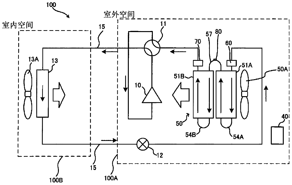
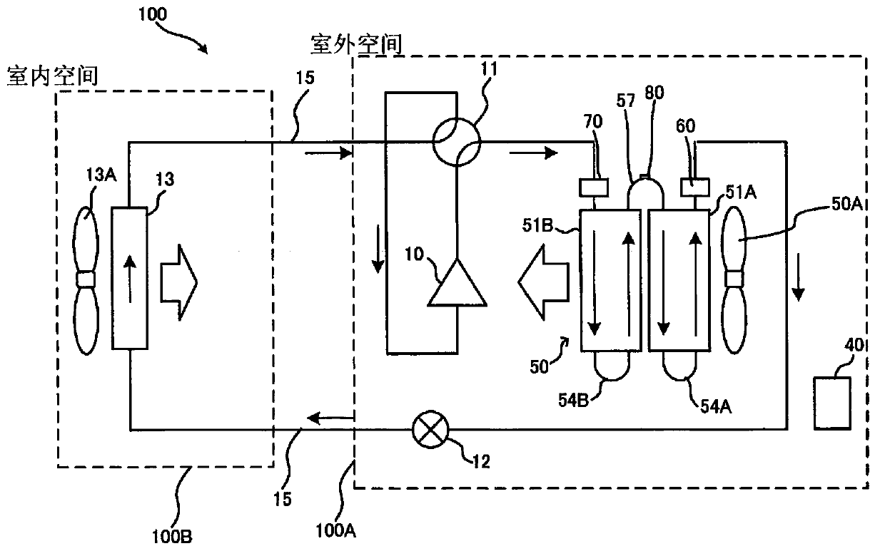
[0030] In addition, the case where the heat source side unit of the present invention is applied to an air conditioner as an example of a refrigeration cycle device will be described below, but it is not limited to such a case, and it can also be applied to other refrigeration cycles...


PUM


Abstract

This heat source-side unit is installed in an inter-column connection member in which a temperature sensor is positioned higher than an intermediate position in a vertical direction of a heat exchanger, among inter-column connection members.

Description

technical field [0001] The present invention relates to a heat source side unit equipped with a heat exchanger including a header, and a refrigeration cycle apparatus including the heat source side unit. Background technique [0002] A heat exchanger is mounted on a heat source side unit included in a refrigeration cycle device such as an air conditioner or a water heater. Generally, in order to reduce the pressure loss of the refrigerant flowing in the heat transfer tubes, the heat exchanger has a flow path (path) in which a plurality of heat transfer tubes are arranged in parallel. A header corresponding to the number of paths is provided at the refrigerant inlet and the refrigerant outlet of each heat transfer tube. In addition, a temperature sensor for measuring the temperature of the refrigerant flowing through the heat transfer tubes may be provided in the header. [0003] As such a heat exchanger, for example, the following heat exchanger has been proposed, that is,...

Claims


Application Information

Patent Timeline
IPC IPC(8): F28F9/00F25B49/02
CPCF25B49/02F28F9/00F28D1/0435F28D1/0476F28D2021/0068F28F9/0204F28F9/0221F28F9/0243F28D1/0452F28F9/262F25B2313/0253F25B2313/0315F28F1/128F28F9/0278F28F2215/12
Inventor 加藤央平丹田翼高村将广坂部雄大
Owner MITSUBISHI ELECTRIC CORP
Why Eureka
Try Eureka