Linkage drive type mop cleaning seat sewerage system
A technology of linkage drive and sewage system, applied in the field of mops, can solve the problems of troublesome operation, dirty hands, inconvenient use, etc., and achieve the effect of simple operation, easy use and good effect.
- Summary
- Abstract
- Description
- Claims
- Application Information
AI Technical Summary
Problems solved by technology
Method used
Image

Examples
Embodiment 1
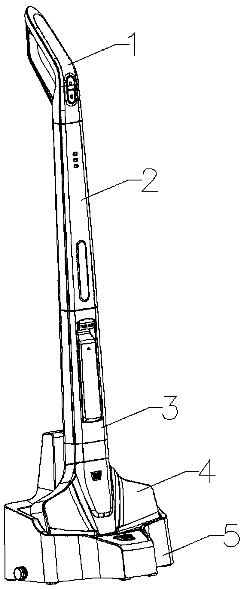
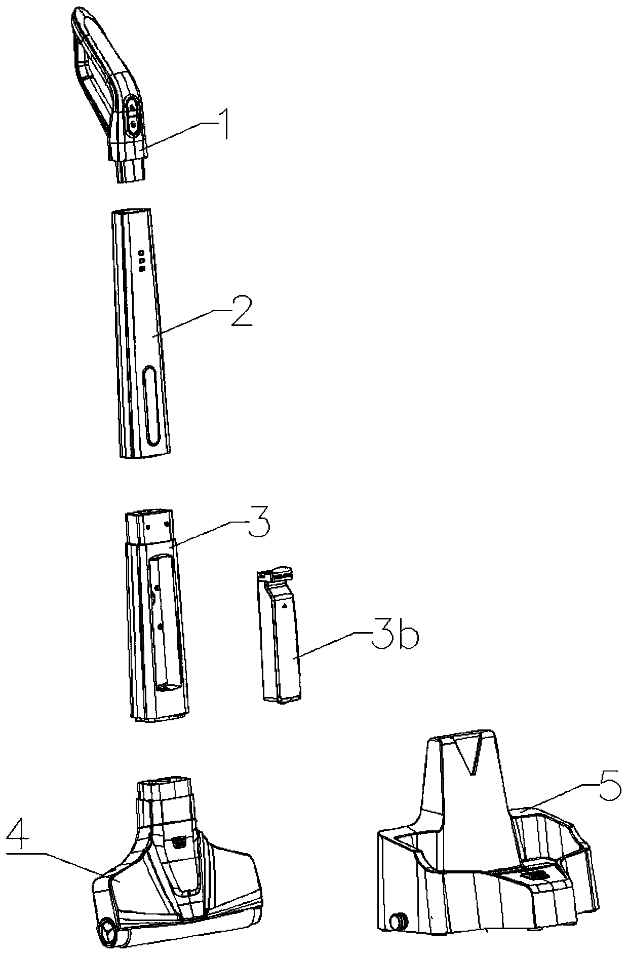
[0035] Such as figure 1 and figure 2 As shown, a mop that can be cleaned automatically includes a mop rod assembly, a mop head assembly 4 and a cleaning seat assembly 5, the mop head assembly 4 is arranged at the lower end of the mop rod assembly, and the cleaning seat assembly 5 is used to place and clean the mop head assembly 4. The mop rod assembly includes at least two connecting sections, and the at least two connecting sections are detachably connected to each other.
[0036] In order to facilitate packaging and transportation during transportation and reduce the size of the entire package, the mop rod assembly is formed by detachable multi-section assembly, and the specific division into several sections depends on the design. In this embodiment, as a specific preferred solution, the mop rod assembly includes three connecting segments, the three connecting segments are the handle segment assembly 1, the upper segment rod assembly 2 and the lower segment rod assembly ...
Embodiment 2
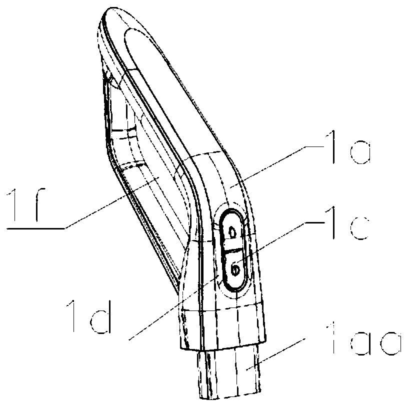
[0038] Such as image 3 and Figure 4 The above-mentioned handle section assembly 1 shown has a hollow handle section shell 1a, the lower end of the handle section shell 1a forms a plug-in section 1aa, the plug-in section 1aa is tubular, and the inside of the handle section shell 1a passes through the plug-in section 1aa Connected to the outside, an elastic arm 1ab for connection and locking is formed on the plug-in section 1aa, and a protrusion for connection and locking is formed on the outer surface of the elastic arm 1ab. As a preference, a switch circuit board 1b is arranged inside the handle section casing 1a, and correspondingly, a switch button 1c is arranged on the handle section casing 1a. As a preference, a switch button through hole is provided at the place where the switch button 1c is placed on the handle section shell 1a, a button setting plate 1d is arranged on the switch button through hole, a switch button 1c is arranged on the button setting plate 1d, and t...
Embodiment 3
[0041] Such as Figure 5 , Figure 6 and Figure 7 The above-mentioned upper rod assembly 2 shown has an upper rod housing 2a; one end of the upper rod housing 2a is formed with an upper slot 2aa for plugging in with the handle segment assembly 1, and the side wall of the upper slot 2aa is provided with a useful In the card slot 2ab that cooperates with the elastic arm 1ab, the upper rod housing 2a is also provided with a handle segment release button 2b for releasing the elastic arm 1ab, and one end of the handle segment release button 2b extends into the card slot 2ab; the upper segment rod The other end of the housing 2a is formed with a lower slot 2c which is inserted into the lower rod assembly 3 . Preferably, the handle segment release key 2b includes a key cap 2ba and a key rod 2bb, and the key rod 2bb extends into the engaging groove 2ab. Preferably, the keycap 2ba penetrates through the wall plate of the upper lever housing 2a, and the lower end edge of the keycap ...
PUM
 Abstract
Description
Claims
Application Information
 - R&D Engineer
- R&D Manager
- IP Professional
- Industry Leading Data Capabilities
- Powerful AI technology
- Patent DNA Extraction
Browse by: Latest US Patents, China's latest patents, Technical Efficacy Thesaurus, Application Domain, Technology Topic.
© 2024 PatSnap. All rights reserved.Legal|Privacy policy|Modern Slavery Act Transparency Statement|Sitemap