Gas-liquid two-phase flow distribution control apparatus and gas-liquid two-phase flow distribution control method

A distribution control device, a technology of gas-liquid two-phase flow, applied in separation methods, liquid degassing regulation/control, chemical instruments and methods, etc. Overcome the effect of different resistance characteristics on distribution, distribution and uniform phase holdup

Pending Publication Date: 2019-08-30
CHINA PETROLEUM & CHEM CORP +1
View PDF4 Cites 5 Cited by
  • Summary
  • Abstract
  • Description
  • Claims
  • Application Information

AI Technical Summary

Problems solved by technology

First, the gas-liquid two-phase flow is separated into single-phase gas and single-phase liquid, and distributed to branch pipelines in proportion, but the relative volume is large and cannot be used in a limited space
[0004] To sum up, there are many patents and methods for evenly distributing each phase of two-phase flow to each branch. Each has its own characteristics and scope of application. The distribution method of different phase holdup and different flow rate has not been reported

Method used


Image

  • Gas-liquid two-phase flow distribution control apparatus and gas-liquid two-phase flow distribution control method
  • Gas-liquid two-phase flow distribution control apparatus and gas-liquid two-phase flow distribution control method
  • Gas-liquid two-phase flow distribution control apparatus and gas-liquid two-phase flow distribution control method

Examples


Embodiment Construction

[0026] The following will clearly and completely describe the technical solutions in the embodiments of the present invention with reference to the accompanying drawings in the embodiments of the present invention. Obviously, the described embodiments are only some, not all, embodiments of the present invention. Based on the embodiments of the present invention, all other embodiments obtained by persons of ordinary skill in the art without making creative efforts belong to the protection scope of the present invention.

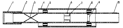
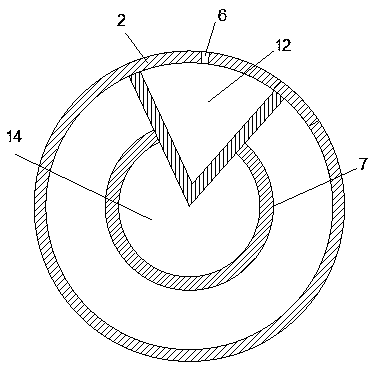
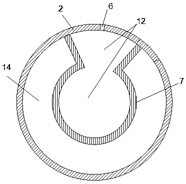
[0027] according to Figures 1 to 7 As shown, the gas-liquid two-phase flow distribution control device and method include a center pipe 2 and a swirl vane 3 installed inside the center pipe, and also include a gas-liquid diversion outer pipe 4, a second upper resistance control valve 5, a first resistance The control valve 6, the phase holdup control device 7, the second lower resistance control valve 8, and the third resistance control valve 9, the phase hol...


PUM


Abstract

The invention discloses a gas-liquid two-phase flow distribution control apparatus and a gas-liquid two-phase flow distribution control method. The apparatus comprises a center pipe, swirling flow blades installed inside the center pipe, a gas-liquid flow dividing outer pipe, a first resistance control valve, a second upper resistance control valve, a second lower resistance control valve, a thirdresistance control valve and a phase holdup control device, wherein the phase holdup control device and the third resistance control valve are both arranged inside the center pipe, the phase holdup control device is positioned below the swirling flow blades, the third resistance control valve is positioned below the phase holdup control device, the gas-liquid flow dividing outer pipe is sleeved on the outer portion of the center pipe, a buffer annulus is formed between the gas-liquid flow dividing outer pipe and the center pipe, and the second upper resistance control valve and the second lower resistance control valve are arranged in the buffer annulus. According to the present invention, with the apparatus and the method, the influence of the different resistance characteristics of various distribution branches on the distribution is fundamentally overcome, and the uniform or non-uniform holdup distribution of the gas-liquid two-phase fluid under different flow rates is achieved.

Description

technical field [0001] The invention relates to a gas-liquid two-phase fluid distribution and control device, in particular to a gas-liquid two-phase flow distribution control device and method. Background technique [0002] Gas-liquid two-phase flow exists widely in many industrial fields such as petroleum and chemical industry, and it is necessary to distribute the flow of gas-liquid two-phase flow. The broad requirement is to overcome the phase separation phenomenon of gas-liquid two-phase fluid in the distribution process and realize different flow distribution under the same phase holdup. At present, there are many patents and methods related to this aspect at home and abroad, each with its own advantages and disadvantages. However, in the petroleum industry, such as in the steam injection development process of thermal recovery wells, it is necessary to realize the distribution of different flow rates under unequal phase holdups, and to overcome phenomena such as gas p...

Claims


Application Information

Patent Timeline
Patent Type & Authority Applications(China)
IPC IPC(8): B01D19/00B01D45/16B01D45/18
CPCB01D19/0057B01D19/0063B01D45/16B01D45/18
Inventor 刘明张全胜赵晓谢志勤戴宇婷王超张鹏李友平姜泽菊逯国成
Owner CHINA PETROLEUM & CHEM CORP
Why Eureka
Try Eureka