
An online hot standby pressure regulating device for a refined oil pipeline decompression station

A technology of pressure regulating device and refined oil, applied in the field of pipeline system, can solve the problems such as the inability of relatively smooth transition of pressure, violent movement of regulating valve, and violent fluctuation of process operation, so as to reduce equipment investment and construction cost, and save space. , The effect of reducing the construction process

Active Publication Date: 2020-07-10
BC P INC CHINA NAT PETROLEUM CORP +2
View PDF6 Cites 0 Cited by
  • Summary
  • Abstract
  • Description
  • Claims
  • Application Information

AI Technical Summary

Problems solved by technology

[0004] The pressure regulation system of this cold standby mode has the following problems: 1) The two-way pressure regulation system is cold standby. When the active / standby pressure regulating system needs to be switched, the active / standby switch is performed through the upstream process switch valve, At this time, the regulating valve moves violently, and the pressure cannot be transferred relatively smoothly, and there is even a risk of overpressure or water hammer behind the valve; 2) In the cold standby mode, manual intervention is too dependent. When a road failure needs to start the backup road, if the personnel cannot Putting the backup line into use will cause severe fluctuations in process operation, and even trigger water hammer, and the entire line will stop transmission; 3) Not all system failures can be uploaded in the form of signals. The system cannot be put into use in time, thus causing a safety hazard to the entire pressure regulating system

Method used


Image

  • An online hot standby pressure regulating device for a refined oil pipeline decompression station

Examples


Embodiment Construction

[0031] The present invention will be described in further detail below through specific embodiments and in conjunction with the accompanying drawings.

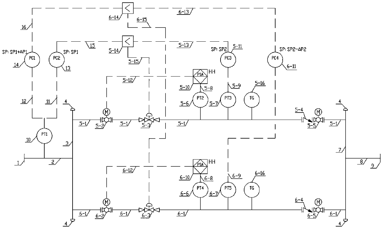
[0032] Such as figure 1 As shown, an online thermal standby pressure regulating device for a product oil pipeline decompression station according to an embodiment of the present invention includes: a first process pipeline 2 and a second process pipeline 8, one end of the first process pipeline 2 is connected to the first flange 1 , the other end of the first process pipeline 2 is connected with the first manifold 3, the fifth pressure transmitter 10 is arranged on the first process pipeline 2, one end of the second process pipeline 8 is connected with the second flange 9, the second process pipeline The other end of 8 is connected to the second manifold 7, and the active pressure regulating branch pipeline 5-1 and the spare pressure regulating branch pipeline 6-1 are connected between the first manifold 3 and the second manif...


PUM


Abstract

The invention discloses an online hot standby pressure regulating device of a product oil pipeline pressure reducing station. The device comprises two headers between two process pipelines, two pressure regulating branch pipelines between the two headers, a process belt executing mechanism ball valve, a pressure adjusting valve, two pressure transmitters, a local thermometer, a check valve and a process belt executing mechanism ball valve are sequentially connected on each pipeline in series, wherein each pressure transmitter is connected with a pressure controller, and high-pressure relays are connected between the process belt executing mechanism ball valves and the first pressure transmitters; the first process pipeline is connected with a pressure transmitter, and the pressure transmitter is connected with two pressure controllers; and the two pressure controllers and the pressure adjusting valve are connected with a low selector. The device has the beneficial effects that a pressure regulating system can automatically complete the whole switching process of an in-use path / a standby path on line, manual intervention is not needed, smooth transition is achieved, reliability is high, continuity, stability and reliability of detection and hot standby pressure regulating control are improved, and operation and maintenance are facilitated.

Description

technical field [0001] The invention relates to the technical field of pipeline systems, in particular to an online hot standby pressure regulating device for a product oil pipeline decompression station. Background technique [0002] After the long-distance refined oil pipeline crosses the high point along the line, a decompression station is usually set up. There are two main purposes of setting up the pressure regulating device of the decompression station: 1. To ensure that the back pressure of the pipeline on the entry side of the decompression station is sufficiently high, so that the pressure at the high point along the line is greater than 0.2MPa, so as to prevent the pressure at the high point along the line from being pulled out; 2. Ensure that the outlet pressure of the decompression station is lower than the outlet design pressure (usually 0.5MPa lower than the outlet design pressure). [0003] In the past, the switching mode of the active road and the standby r...

Claims


Application Information

Patent Timeline
Patent Type & Authority Patents(China)
IPC IPC(8): F17D3/01
CPCF17D3/01
Inventor 聂中文孔芋丁姜念琛西敬军黄薇薇冯骋单超
Owner BC P INC CHINA NAT PETROLEUM CORP
Learn More