Battery well for monitoring valve chamber and method of use thereof

A battery and valve chamber technology, applied in the field of battery wells, can solve the problems affecting the reliability and safety of equipment, inability to supply power to the equipment, and water inflow to the battery, so as to reduce equipment investment and construction costs, reduce construction procedures and materials, and provide convenience. The effect of operation and maintenance

Active Publication Date: 2019-06-11
BC P INC CHINA NAT PETROLEUM CORP +2
View PDF4 Cites 0 Cited by
  • Summary
  • Abstract
  • Description
  • Claims
  • Application Information

AI Technical Summary

Problems solved by technology

[0002] For the monitoring valve chamber in the oil and gas long-distance pipeline project, the battery well in the prior art uses a rectangular well cover. In areas with continuous rain, excessive rainfall will cause rainwater to leak into the battery well from the side of the well cover. Related equipment power supply, on-site communication interruption
In addition, in the cold area, the average sunshine time is short and the sunlight intensity is low, which leads to insufficient power absorbed by the solar panels and cannot continue to supply power to the battery, which makes the battery power supply to the equipment interrupted, resulting in the RTU being unable to communicate with the station control system normally. , the data transmission is interrupted, and the control center cannot monitor the status of the monitoring valve chamber, seriously affecting the stable and continuous operation of the station
Therefore, the use of the original battery well cover and the practice of not installing charging equipment near the battery well will affect the data transmission of the RTU valve chamber and affect the reliability and safety of the equipment

Method used


Image

  • Battery well for monitoring valve chamber and method of use thereof
  • Battery well for monitoring valve chamber and method of use thereof

Examples


Embodiment 1

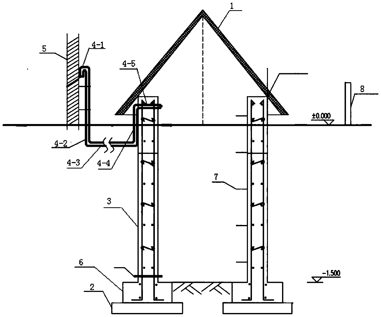
[0055] Example 1, such as figure 1 As shown, a battery well for monitoring valve chambers in an embodiment of the present invention includes:

[0056] The manhole cover 1 is conical and located above the ground. The surface of the manhole cover 1 is provided with an anti-corrosion layer. The setting of the anti-corrosion layer can further prolong the service life of the manhole cover;

[0057] The base 2, which is located in the foundation pit below the ground;

[0058] The foundation 3 is located on the base 2, the bottom of the foundation 3 is connected to the top of the base 2, the top of the foundation 3 is located above the ground, and the top of the foundation 3 is sealed and connected to the opening of the well cover 1, and several steel bars are preset in the foundation 3, and the base 2 and the base 3 to form an accommodation space for accumulating batteries;

[0059] Exhaust pipe, one end of the exhaust pipe runs through the upper part of the foundation 3 and is lo...

Embodiment 2

[0093] Embodiment 2, a method of using a battery well for monitoring a valve chamber, comprising:

[0094] Step 1, fixing the base 2 in the foundation pit below the ground;

[0095] Step 2, placing the foundation 3 preset with several steel bars on the base 2, pouring the foundation 3 with concrete, and ensuring that the top of the foundation 3 is above the ground, and the bottom of the foundation 3 is connected with the top of the base 2;

[0096] Step 3, one end of the exhaust pipe runs through the upper part of the foundation 3 horizontally and is located above the ground, the other end of the exhaust pipe passes through the ground and then leads to above the ground, and the exhaust pipe exposed outside the well body and located above the ground is fixed to the monitoring valve On the outer wall 5 of the chamber, and the opening of the port at one end of the exhaust pipe faces the inside of the well body, and the opening of the port at the other end of the exhaust pipe face...


PUM


Abstract

The invention discloses an accumulator well of a monitoring valve room. The accumulator well comprises a well cover, bases, foundations, exhaust pipes, an accumulator charging device and a solar panel. The well cover is located above the ground; the bases are located in a foundation pit under the ground; the foundations are located on the bases, the bottoms of the foundations are connected with the tops of the bases, the tops of the foundations are located above the ground, and containing spaces are formed by the bases and the foundations; one ends of the exhaust pipes penetrate through the upper portions of the foundations and are located above the ground, and the other ends of the exhaust pipes are located outside the well cover and located above the ground; the accumulator charging device is located outside the well cover and above the ground and connected with accumulators in the containing spaces; and the solar panel is located outside the well cover and the monitoring valve roomand connected with the accumulator charging device. The invention further discloses a using method of the accumulator well of the monitoring valve room. The accumulator well of the monitoring valve room has the beneficial effects that the phenomenon that the amount of rainwater is excessively large, and consequently water in the accumulator well leaks is prevented; and it can be ensured that the accumulators continuously supply power to electric equipment under the condition that the sunshine time is short and the sunshine intensity is low.

Description

technical field [0001] The invention relates to the technical field of pipeline systems, in particular to a battery well for monitoring valve chambers and a method for using the same. Background technique [0002] For the monitoring valve chamber in the oil and gas long-distance pipeline project, the battery well in the prior art uses a rectangular well cover. In areas with continuous rain, excessive rainfall will cause rainwater to leak into the battery well from the side of the well cover. Related equipment is powered, and on-site communication is interrupted. In addition, in the cold area, the average sunshine time is short and the sunlight intensity is low, which leads to insufficient power absorbed by the solar panels and cannot continue to supply power to the battery, which makes the battery power supply to the equipment interrupted, resulting in the RTU being unable to communicate with the station control system normally. , the data transmission is interrupted, and t...

Claims


Application Information

Patent Timeline
Patent Type & Authority Patents(China)
IPC IPC(8): E02D29/12H02J7/00H02J7/35
CPCE02D29/12H02J7/0029H02J7/00304H02J7/0034H02J7/0077H02J7/35
Inventor 聂中文赵晓鹰聂世新邹永胜冷绪林梁俊
Owner BC P INC CHINA NAT PETROLEUM CORP
Why Eureka
Try Eureka