Design method of a steam boiler

A technology for a steam boiler and a design method, which is applied to steam boilers, steam generation methods using pressure combustion, steam generation, etc. flow effect and other problems, to achieve the effect of good separation effect, stable flow, and simple structure

Active Publication Date: 2020-11-17
中盐昆山有限公司
View PDF6 Cites 0 Cited by
  • Summary
  • Abstract
  • Description
  • Claims
  • Application Information

AI Technical Summary

Problems solved by technology

The impact phenomenon will cause large noise vibration and mechanical shock, causing damage to the equipment
[0006] A variety of riser devices to solve the above problems have also been designed in the previous application, such as 2017102546447 multi-pipe type, but this kind of device is found in operation, because the pipes are tightly combined, so the space formed between the three pipes A is relatively small, because the space A is formed by the convex arc of three pipes, so most of the space A is narrow, which will make it difficult for the fluid to enter and pass through, resulting in a short circuit of the fluid, which affects the heat exchange of the fluid and cannot play a good role. Steady flow
Simultaneously because the many tubes of above-mentioned structure are combined together, manufacture difficulty
Another example is the 2017102666326 structure. Although this structure solves the fluid short circuit phenomenon, there is a problem that the flow area is greatly reduced, resulting in an increase in flow resistance.
Another example is the ring-shaped flow stabilization device of 2017102949490. In the ring structure, the flow stabilization device adopts a ring structure, which leads to uneven separation of the annulus of the flow stabilization device in the circumferential direction, and because of the ring structure, the positions of the four angles of the annulus Acute angles less than 90 degrees occur, which can cause problems with fluid flow short circuits in the acute angles less than 90 degrees
[0007] In view of the above problems, the present invention improves on the basis of the previous invention, and provides a new steam boiler and its design method, thereby solving the problem of low heat absorption efficiency of the rising tube

Method used


Image

  • Design method of a steam boiler
  • Design method of a steam boiler
  • Design method of a steam boiler

Examples


Embodiment Construction

[0046] The specific embodiments of the present invention will be described in detail below in conjunction with the accompanying drawings.

[0047] In this article, if there is no special explanation, when it comes to formulas, " / " means division, and "×" and "*" mean multiplication.

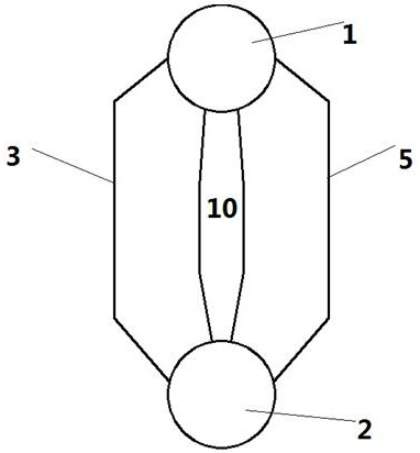
[0048] Such as figure 1The aforementioned steam boiler includes an upper drum 1 and a lower drum 2 , and the ascending tube 3 and the downcomer 5 connect the upper drum 1 and the lower drum 2 . Water enters the downcomer 5 from the upper drum 1 . The water flows down in the downcomer and is collected in the lower drum 2. The riser 3 of the boiler is heated by the combustion of fuel in the combustion chamber 10 of the furnace. The heat absorbed by the riser 3 causes the liquid inside the tube to boil, thereby creating a two-phase mixture of water and steam. The two-phase mixture in the riser 3 reaches the upper drum 1 . The supercooled water released from the water supply pipe (not shown) in ...


PUM


Abstract

The invention provides a method for designing a steam boiler, which includes an upper drum and a lower drum, and a riser and a downcomer connected between the upper drum and the lower drum, a flow stabilization device is arranged in the riser, and the stabilizer The flow device is composed of a square through hole and a regular octagonal through hole. As the diameter of the riser increases, the side length of the square through hole also increases. The invention provides a steam boiler design method with a new-type structure of a flow stabilizing device. The boiler designed by this method can enhance heat transfer when there is a vapor-liquid two-phase flow in the riser pipe, and at the same time weaken the vibration of the riser pipe and reduce the noise level.

Description

technical field [0001] The present invention is a project commissioned by colleges and universities to carry out research and development. The invention belongs to the field of steam generation, in particular to a steam boiler, and belongs to the field of IPC classification number F22. Background technique [0002] The circuit that receives heat from the furnace and makes the fluid flow from a low level to a high level is called an "ascending loop", while the circuit that receives heat and makes a fluid flow from a high level to a low level is called a "falling loop". A circuit consists of a pipe or a group of pipes leading from a common point, such as a header or steam drum, and terminating at a common point, also a header or drum. [0003] In most natural circulation boiler designs, the heated tubes making up the evaporating section generally provide upward flow, but in multi-drum boilers, the descending heated tubes of the evaporator bundle do not. In this type of boile...

Claims


Application Information

Patent Timeline
Patent Type & Authority Patents(China)
IPC IPC(8): F22B1/22F22B31/08
CPCF22B1/22F22B31/08
Inventor 赵伟谷潇潇江程李红云胡全君
Owner 中盐昆山有限公司
Why Eureka
Try Eureka