
A Method for Determining Error Coefficients of Inertial Devices

An inertial device and error coefficient technology, which is applied in the field of inertial device error coefficient determination, can solve problems such as estimation deviation, and achieve the effects of small storage, good application range and engineering value, and high-precision estimation

Active Publication Date: 2021-04-13
BEIJING INST OF AEROSPACE CONTROL DEVICES
View PDF10 Cites 0 Cited by
  • Summary
  • Abstract
  • Description
  • Claims
  • Application Information

AI Technical Summary

Problems solved by technology

[0004] The technical problem to be solved by the present invention is: to overcome the deficiencies of the prior art, to provide a method for determining the error coefficient of inertial devices, to overcome the existing Kalman filter which is susceptible to dynamic noise w(t) and measurement noise v(t) The covariance matrix Q of n and R n Insufficiency that may lead to biased valuations

Method used


Image

  • A Method for Determining Error Coefficients of Inertial Devices
  • A Method for Determining Error Coefficients of Inertial Devices
  • A Method for Determining Error Coefficients of Inertial Devices

Examples


Embodiment 1

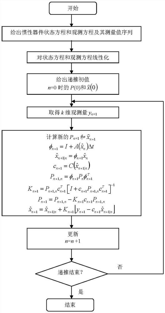
[0055] A method for determining an error coefficient of an inertial device, the inertial device including but not limited to an accelerometer or a gyroscope or an integrated navigation system; comprising the following steps:

[0056] S1, with inertial device error coefficient as state variable, establish state equation and observation equation; The state equation and observation equation of described inertial device error coefficient are:

[0057]

[0058] In the formula, t is time, x(t) is a state vector composed of error coefficients of inertial devices, is the differential of x(t) relative to time t, f(x(t)) is the state equation function composed of x(t), w(t) is the dynamic noise, y is the observed quantity, h(x) is the state equation function composed of x(t) (t) is the observation equation function, and v(t) is the measurement noise.

[0059] S2, the state equation described in S1 and observation equation are carried out linearization, the function matrix after car...

Embodiment 2

[0088] A computer-readable storage medium, on which a computer program is stored, and when the program is executed by a processor, the steps of the method for determining the error coefficient of the above-mentioned device are realized.

Embodiment 3

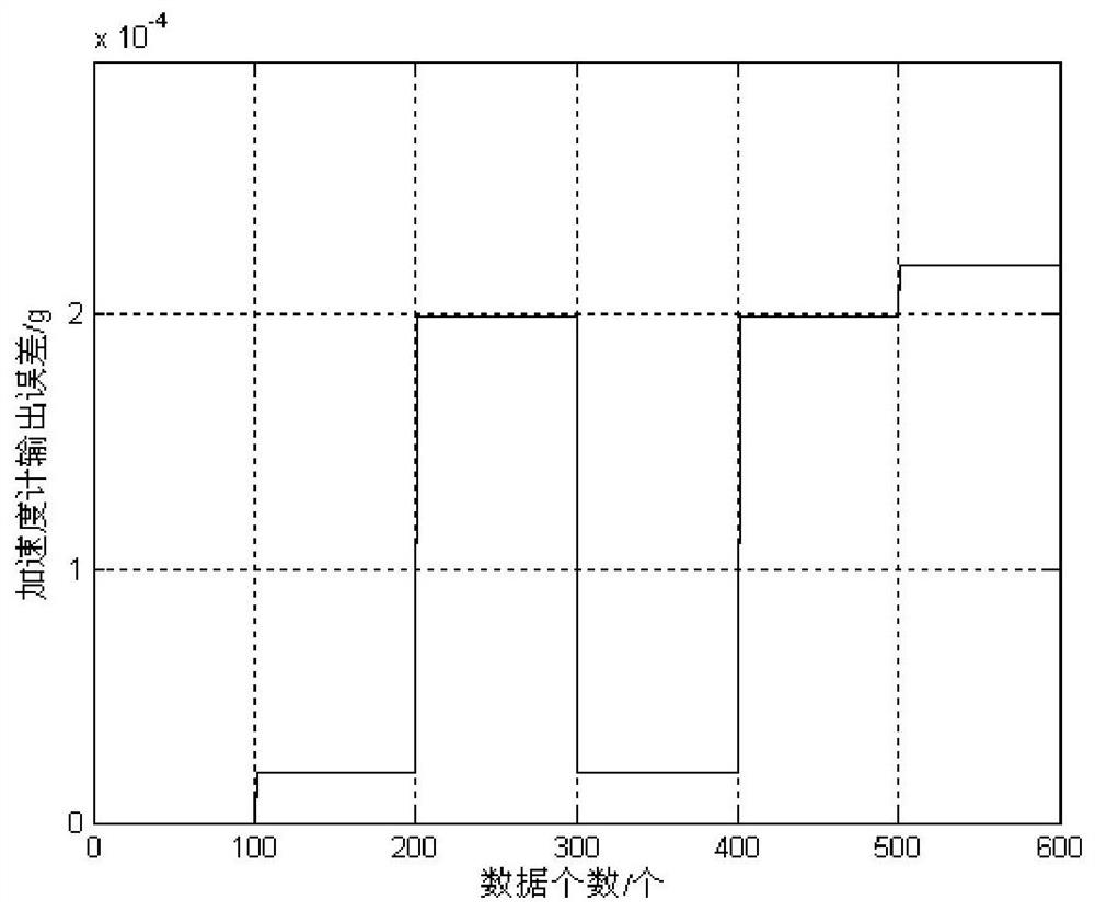
[0090] Taking accelerometer error calibration as an example, the specific process is as follows figure 1 As shown, the accelerometer output error equation is designed as

[0091] A x =k 0x +δk x a x +k yx a y +k zx a z

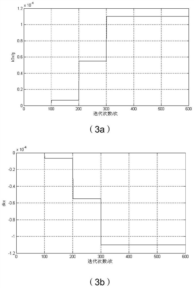
[0092] In the formula, a x 、a y 、a z is the projected component of the gravitational acceleration corresponding to the three axes OX, OY, and OZ of the accelerometer housing coordinate system OXYZ; k 0x is the zero bias of the accelerometer; δk x is the linearity of the accelerometer; k yx and k zx are the installation error angles of the accelerometer input axis relative to OY and OZ; A x is the measurement error of the accelerometer.

[0093] Take the state variable as

[0094]

[0095] Because above-mentioned 4 error coefficients are all constant value, have nothing to do with time, then according to state equation and observation equation described in the present invention are:

[0096]

[0097] That is, the state equation function ...


PUM


Abstract

The invention relates to a method for determining the error coefficient of an inertial device. By linearizing the nonlinear state equation and the observation equation, and using the extended recursive least squares method to calculate the error coefficient of the inertial device, the existing Kalman filter estimation value is overcome. Not the only disadvantage, this method can adapt to the situation when the state equation and the observation equation are nonlinear functions, and can also satisfy the situation when the state equation and the observation equation are linear functions. This method can be calculated in real time, is easy to realize, and has the value of engineering practical application.

Description

technical field [0001] The invention relates to a method for determining an error coefficient of an inertial device, belonging to the technical field of aerospace. Background technique [0002] At present, the inertial navigation of aerospace vehicles mainly adopts strapdown systems or platform systems composed of gyroscopes and accelerometers. Before live ammunition flight, it is necessary to calibrate the error coefficients of the gyroscope and accelerometer on the ground, and the accuracy of inertial navigation can be effectively improved through error compensation according to the calibration results. At present, in the actual flight navigation test of the inertial device calibrated on the ground, there is still a large deviation between the theoretical value of the speed and position calculated according to the telemetry data and the real flight speed and position value obtained from the external test, and the so-called "Heaven and earth don't agree" situation. After ...

Claims


Application Information

Patent Timeline
Patent Type & Authority Patents(China)
IPC IPC(8): G01C25/00G01C21/16
CPCG01C21/16G01C25/00
Inventor 魏宗康
Owner BEIJING INST OF AEROSPACE CONTROL DEVICES
Learn More