High speed bearing friction torque measuring system

A technology of friction torque and high-speed bearings, which is applied in mechanical bearing testing, measuring devices, torque measurement, etc., can solve the problems of inaccurate measurement of bearing friction torque and high axial load, etc., to reduce contact, reduce difficulty, The effect of improving loading capacity

Inactive Publication Date: 2019-08-30
HARBIN INST OF TECH
View PDF7 Cites 7 Cited by
  • Summary
  • Abstract
  • Description
  • Claims
  • Application Information

AI Technical Summary

Problems solved by technology

[0003] The purpose of the present invention is to solve the problem that the existing test bench for measuring bearing friction torque is limited by the bearing structure and bearing capacity, the axial load applied to the bearing cannot reach a high level, and finally the bearing friction torque cannot be accurately measured. question
High-speed bearing friction torque measurement system is now available

Method used


Image

  • High speed bearing friction torque measuring system
  • High speed bearing friction torque measuring system
  • High speed bearing friction torque measuring system

Examples


specific Embodiment approach 1

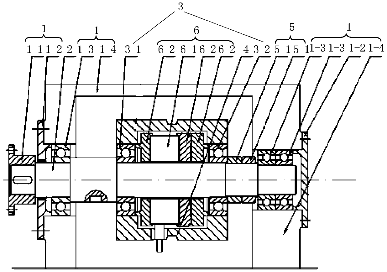
[0018] Specific implementation mode one: refer to figure 1 Describe this embodiment in detail, the high-speed bearing friction torque measurement system described in this embodiment, the system includes a main shaft support device 1, a main shaft 2, a sleeve 4, an axial load application device 5, an axial load measurement device 6 and a tension sensor 7,

[0019] The main shaft supporting device 1 is used to support the main shaft 2, and the two tested bearings 3 are respectively the No. 1 tested bearing 3-1 and the No. 2 tested bearing 3-2,

[0020] The No. 1 tested bearing 3-1, the No. 2 tested bearing 3-2, the axial load applying device 5 and the axial load measuring device 6 are all set on the main shaft 2, and there is a limit step on the main shaft 2 for limiting The axial position of No. 1 tested bearing 3-1,

[0021] The axial load measuring device 6 is arranged between the No. 1 tested bearing 3-1 and the No. 2 tested bearing 3-2, and is used to measure the axial lo...

specific Embodiment approach 2

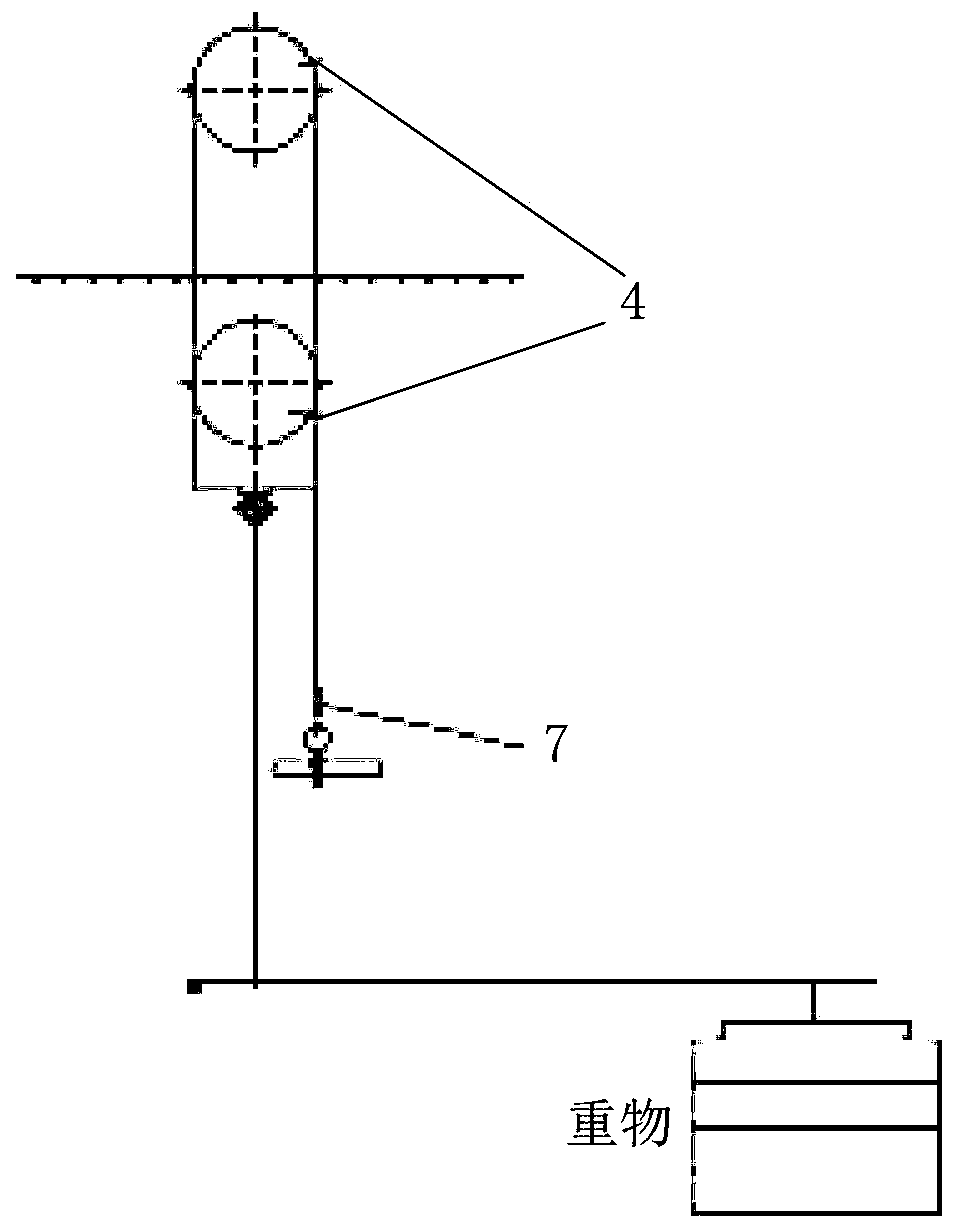
[0030] Specific implementation mode two: refer to figure 2 Describe this embodiment in detail. This embodiment is a further description of the high-speed bearing friction torque measurement system described in Embodiment 1. In this embodiment, the system also includes a radial load application device,

[0031] The radial load applying device is connected to the bottom end of the outer wall of the sleeve 4 through a wire rope, and is used for applying radial load to the two tested bearings 3 .

specific Embodiment approach 3

[0032] Embodiment 3: This embodiment further explains the high-speed bearing friction torque measurement system described in Embodiment 2. In this embodiment, the radial load applying device is realized by using weights.


PUM


Abstract

The present invention discloses a high speed bearing friction torque measuring system, and relates to the field of bearing performance testing. The system solves the problem that a test bench used formeasuring a bearing friction torque is limited by a bearing structure and bearing capacity in the prior design, an axial load applied to the bearing cannot reach a high level, and finally the bearingfriction torque cannot be accurately measured. A limiting step is provided on a main shaft for limiting axial position of the first bearing to be tested, an axial load measuring device is used to measure the axial load force applied to the two bearings under testing, an axial load applying device is used for squeezing and applying the axial load to the second bearing to be tested, a sleeve is sleeved on the axial load measuring device and outside of the two bearings to be tested at the same time, a tension sensor is connected to outer wall of the sleeve through a wire rope, the tension sensoris used to pull the sleeve, when the main shaft rotates, the sleeve is at an equilibrium position to measure the frictional torque of the two bearings to be tested under the axial load. The system isused to measure the frictional torque of the bearings under the axial load.

Description

technical field [0001] The invention relates to a service performance test bearing under high-speed and heavy-load conditions, and can measure the friction moment of the bearing under relatively high axial load and relatively high rotational speed, belonging to the field of bearing performance test. Background technique [0002] At present, there are many test benches for measuring bearing friction torque, which can realize the measurement of friction torque under axial load. In order to reduce the influence of external friction on the accuracy of friction torque measurement under bearing axial load, the tested bearing is tested. Air bearings are usually used for loading, and the measurement accuracy of friction torque can be improved by reducing the introduction of external friction. Force sensors, torque sensors, and displacement sensors can be used to indirectly measure the friction torque of bearings during measurement, but the impact of air bearings is limited. Due to t...

Claims


Application Information

Patent Timeline
Patent Type & Authority Applications(China)
IPC IPC(8): G01M13/04G01L3/04
CPCG01L3/04G01M13/04
Inventor 王黎钦郑德志高靖松
Owner HARBIN INST OF TECH
Why Eureka
Try Eureka