Turbocharger

A technology of turbochargers and turbines, which is applied in the direction of machines/engines, mechanical equipment, engine components, etc., can solve problems such as low efficiency, pollution, and impossibility of high rotor speed, and achieve high speed and high efficiency

Active Publication Date: 2019-06-21
INST OF MACHINERY MFG TECH CHINA ACAD OF ENG PHYSICS
View PDF9 Cites 0 Cited by
  • Summary
  • Abstract
  • Description
  • Claims
  • Application Information

AI Technical Summary

Problems solved by technology

[0002] Turbocharger bearings usually use rolling bearings and sliding bearings. The characteristics of these two bearings have the following problems in the application of turbochargers: due to the existence of lubricating oil, oil leakage is inevitable, which leads to pollution problems ; Due to the existence of friction, the working speed of the rotor cannot be too high and the efficiency is low; due to the existence of wear, the bearing life is short
[0003] In the existing technology, the support of the turbocharger rotor system must include radial support bearings and axial thrust bearings. If the design speed of the rotor system reaches 40,000 RPM (rev / min), the turbocharger used The bearing systems that can meet this working speed are mainly gas static pressure bearings, gas dynamic pressure bearings and hydrostatic bearings (ordinary mechanical bearings cannot meet the requirements of this working speed); Gas media at both ends cause contamination
The axial thrust bearing of the gas dynamic pressure bearing has the problem of insufficient bearing capacity, in which the high-pressure gas at the turbine end and the impeller end are 10MPa and 3MPa respectively, due to the very large pressure difference, there is a large axial force in the rotor system ;Aerodynamic bearings are difficult to meet the requirements as axial thrust bearings

Method used


Image

  • Turbocharger
  • Turbocharger
  • Turbocharger

Examples


Embodiment Construction

[0031] The present invention will be further described in detail below in conjunction with the accompanying drawings, so that those skilled in the art can implement it with reference to the description.

[0032] It should be understood that terms such as "having", "comprising" and "including" as used herein do not entail the presence or addition of one or more other elements or combinations thereof.

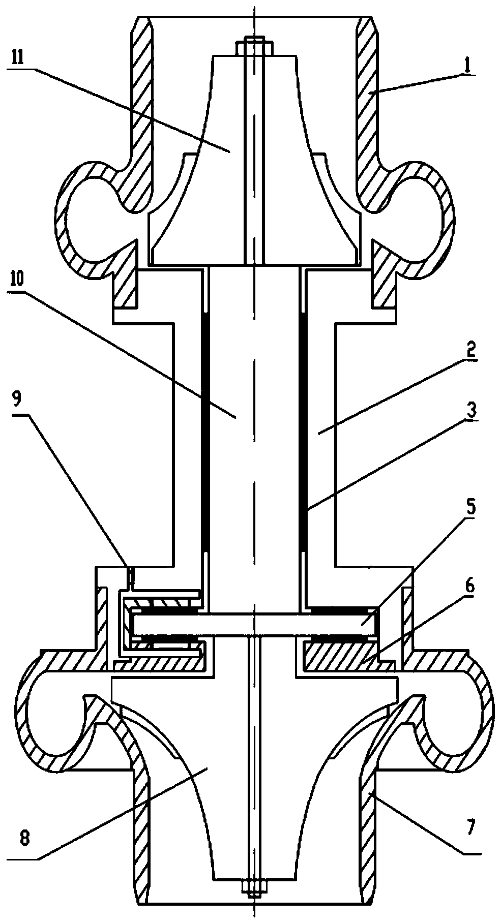
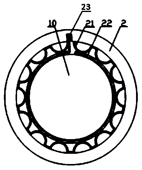
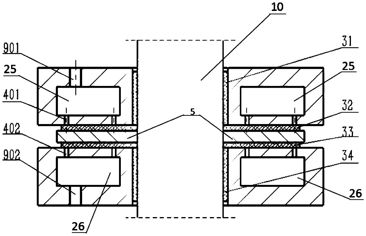
[0033] Figure 1~3 A turbocharger of the present invention is shown, including a turbine housing 7, a turbine 8 arranged in the turbine housing 7, a rotating shaft 10 connected to the turbine 8, a radial thrust bearing 3 sleeved on the rotating shaft 10 and an axial The thrust bearing, and the impeller 11 and the impeller shell 1 connected to the other end of the rotating shaft 10, the radial thrust bearing 3 adopts an aerodynamic foil radial thrust bearing; the axial thrust bearing adopts an aerostatic axial thrust bearing .

[0034] In the above technical scheme, the turbocha...


PUM


Abstract

The invention discloses a turbocharger, comprising a turbine housing, a turbine, a rotary shaft, a radial thrust bearing and an axial thrust bearing, an impeller and an impeller housing, wherein the turbine is arranged in the turbine housing; the rotary shaft is connected with the turbine; each of the radial thrust bearing and the axial thrust bearing sleeves the rotary shaft; the impeller is connected with the other end of the rotary shaft; the radial thrust bearing is an air dynamic pressure foil radial thrust bearing; the axial thrust bearing is an air static pressure axial thrust bearing. The turbocharger has the advantages that a turbocharger rotor system is supported by a combined structure of the air static pressure axial thrust bearing and the air dynamic pressure foil radial thrust bearing, so that the effects of no lubricating oil, high efficiency, high rotation speed and the like are achieved; the air static pressure axial thrust bearing can bear great axial load; two types of gas differing in medium and respectively positioned at a turbine end and an impeller end can be isolated by a high-pressure air film formed by the air static pressure axial thrust bearing; meanwhile, the air dynamic pressure foil radial thrust bearing can be adapted to a high temperature environment, and no cooling device is needed in the turbocharger.

Description

technical field [0001] The invention relates to a turbocharger, in particular to a turbocharger adopting an air dynamic pressure foil radial thrust bearing and an air static pressure axial thrust bearing. Background technique [0002] Turbocharger bearings usually use rolling bearings and sliding bearings. The characteristics of these two bearings have the following problems in the application of turbochargers: due to the existence of lubricating oil, oil leakage is inevitable, which leads to pollution problems ; Due to the existence of friction, the working speed of the rotor cannot be too high and the efficiency is low; due to the existence of wear and tear, the bearing life is short. In some application environments, the turbine end and the impeller end of the turbocharger are two different gas media, and it is required that the two gas media cannot leak each other, and a sealing system needs to be added. The turbocharger works in a high temperature environment, especial...

Claims


Application Information

Patent Timeline
Patent Type & Authority Patents(China)
IPC IPC(8): F16C32/06F01D25/16F02B37/00
CPCF01D25/16F02B37/00F16C32/0622F16C32/0625F16C32/0692F16C2360/24Y02T10/12
Inventor 徐刚舒行军肖永华郑越青蓝河张连新
Owner INST OF MACHINERY MFG TECH CHINA ACAD OF ENG PHYSICS
Why Eureka
Try Eureka