Caster structure

a caster and structure technology, applied in the field of caster structure, can solve the problems of insufficient bonding strength, easy loosening of screws, and damage to the inner and outer rings of the ball bearing, and achieve the effects of small thickness, safe fixing effect, and preventing loosening of screws

Inactive Publication Date: 2018-01-09
CHEN FR
View PDF13 Cites 0 Cited by
  • Summary
  • Abstract
  • Description
  • Claims
  • Application Information

AI Technical Summary

Benefits of technology

[0004]Therefore, it is a primary objective of the present invention to provide a caster passing through the screws of different components to provide a safe fixing effect and to prevent the screws from being loosened similar to a dual-nut effect. The installed screw has a small thickness to lower the center of gravity of a bed surface of a cart, to provide a stable movement when the cart is pushed. The bearing is one capable of bearing a relatively large axial force, and the bearing is limited and positioned during the installation to protect the components, to prevent the bearing from falling out, and to provide an anti-dust effect.
[0005]To achieve the aforementioned object, the present invention provides a caster having a carrying plate installed at the top of the caster, a screw hole formed at the middle of the carrying plate for passing a screw from bottom to top through different components and then screwing and connecting with a nut, and a stop structure for limiting and stopping the nut and the rear end, so that the nut cannot be rotated anymore. Therefore, the invention stops the rear end of the screw by the effect similar to a dual-nut effect to prevent the components from being loosened and to provide a safe fixing effect.
[0006]The present invention is also characterized in that the bearing is a thrust bearing which has a large axial force to bear a larger axial load of the cart and to prevent the bearing from being damaged by the axial load or falling out. The bearing is embedded into a concave cavity of the caster and adjacent stacked components to reduce the installation gap of the bearing and to provide an anti-dust effect of the bearing.

Problems solved by technology

Thus, their bonding strength is relatively insufficient.
When the ball bearing is applied to the caster with an axial load, inner and outer rings of the ball bearing are often damaged by the large vertical pressure, and the balls may even fall out.
As a result, the cart may be stuck to cause an unsmooth movement of the cart.

Method used


Image

  • Caster structure
  • Caster structure
  • Caster structure

Examples


Embodiment Construction

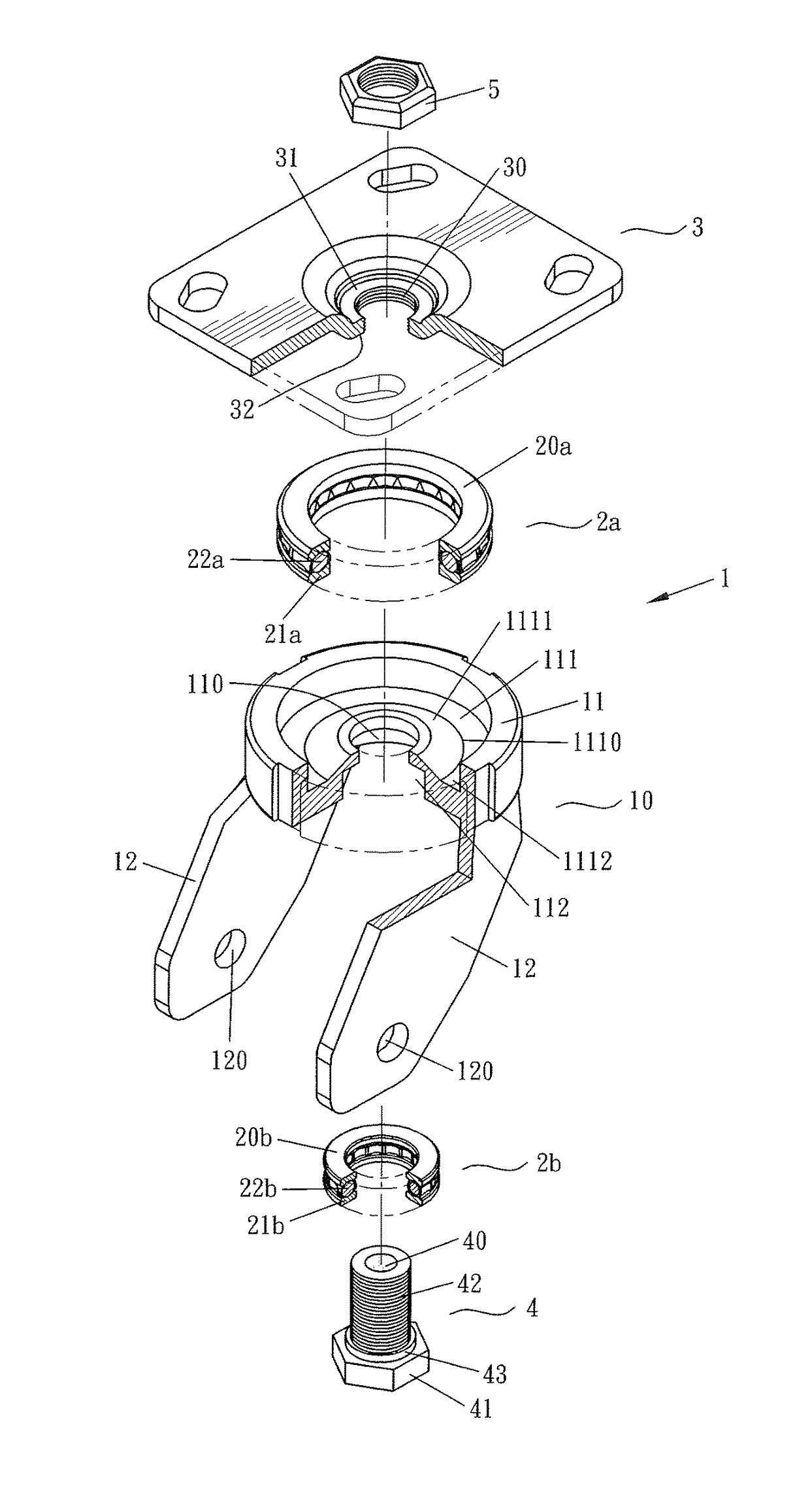
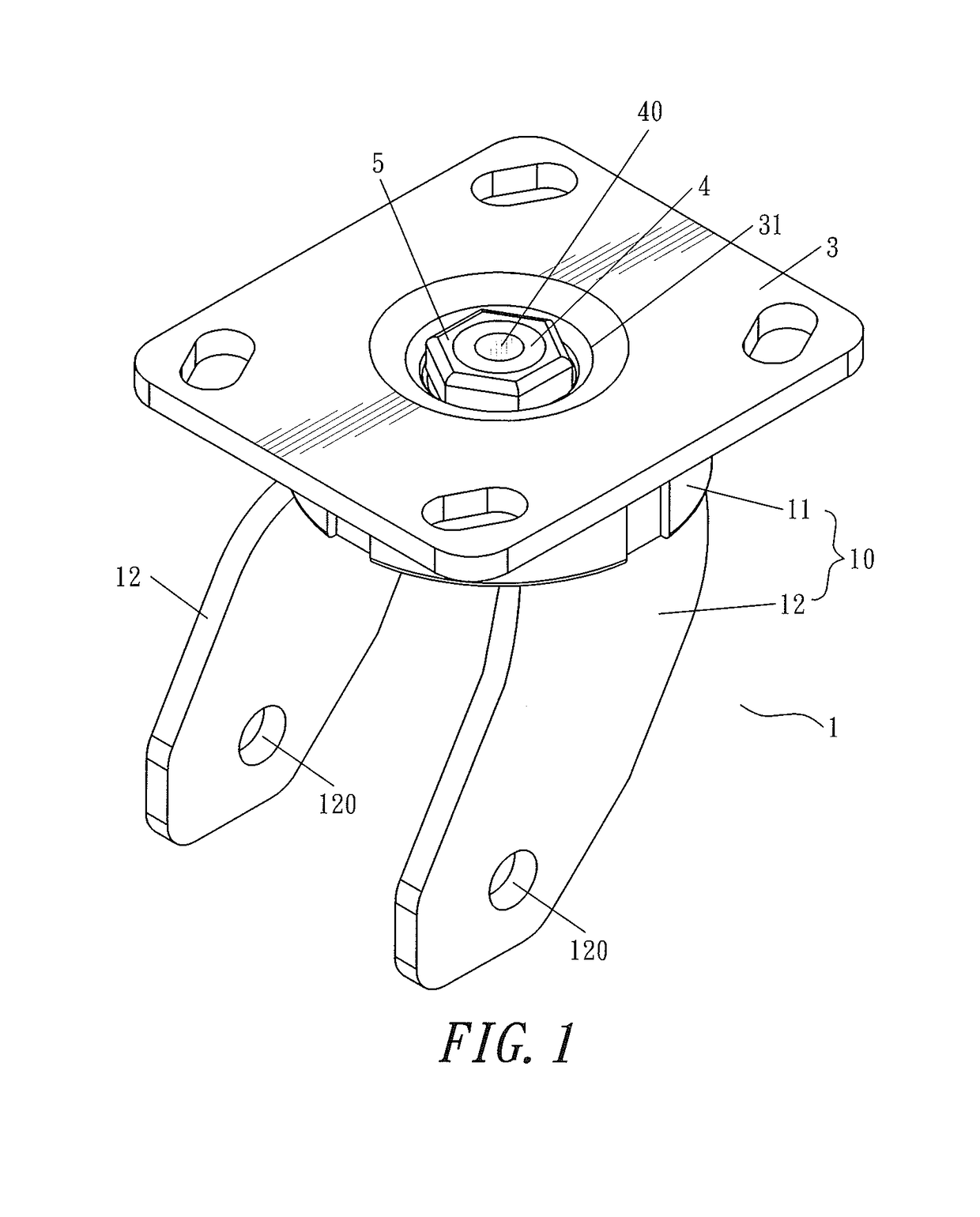
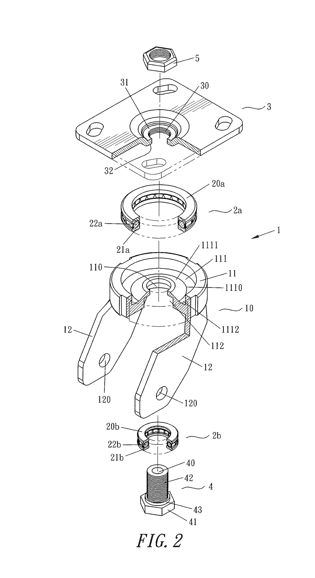
[0012]With reference to FIGS. 1 to 3 for a caster in accordance with a preferred embodiment of the present invention, the caster 1 comprises the following elements:

[0013]A bipod 10 includes a main body 11 and two support legs 12. A through hole 110 is formed at the middle of the main body 11, an upper cavity 111 is downwardly and concavely formed on a top side of the main body 11 and concentrically configured with the through hole 110, and a lower cavity 112 upwardly and concavely formed on a bottom side of the main body 11 and concentrically configured with the through hole 110. A protrusion 1111 is formed between a middle position 1110 on an internal bottom side of the upper cavity 111 and the edge of the through hole 110, so that a limiting interval 1112 is formed on the internal bottom of the upper cavity 111 and from the middle position 1110 to the inner wall on a side of the upper cavity 111. The support leg 12 is fixed to the bottom side of the main body 11 and is disposed on...


PUM


Abstract

A caster structure has a screw hole formed at the middle of a carrying plate and provided for passing, screwing, and pressing a screw, and then screwing and pressing tightly with a nut, so that the installed screw has a smaller thickness to lower the center of gravity of an installed wheel in addition to giving a dual nut fixing effect. The caster has bearings which are mainly thrust bearings for bearing a relatively larger axial gravity to prevent the bearing from being damaged by gravity and the balls from falling out. The bearings are limited and positioned securely to prevent installation gaps and dusts, to maintain a flexible rotation of the caster.

Description

BACKGROUND OF THE INVENTIONField of the Invention[0001]The present invention relates to a caster structure and, more particularly, to the caster passing through the screws of different parts to prevent loosening the screws and providing a safe fixing effect by dual nuts. The screws have a small assembling thickness. Thus, the center of gravity of a bed surface of a cart is lowered to provide a more stable movement when the cart is pushed, and the bearing is limited and positioned to protect and prevent the components of the bearing from falling off and to provide a dust-resisting effect.Description of the Related Art[0002]A caster structure is disclosed in R.O.C. Pat. No. M349338 (hereinafter referred to as Prior Art 1) and R.O.C. Pat. No. M364616 (hereinafter referred to as Prior Art 2). In the Prior Arts 1 and 2, a screw is passed through components of a caster, and the rear end of the screw is fixed by a nut in order to connect the components securely. However, the screw is fixed...

Claims


Application Information

Patent Timeline
Patent Type & Authority Patents(United States)
IPC IPC(8): B60B33/00
CPCB60B33/006B60B33/0068B60B33/0057B60B2380/12Y10T16/186F16C19/10B60B33/0042
Inventor CHEN, FRANK
Owner CHEN FR
Why Eureka
Try Eureka