A core cementation mold and its experimental method for performance evaluation of sand consolidation formula

An experimental method and core technology, applied in the field of oil well sand control, can solve the problems of inability to expand naturally, multiple transverse cracks and cavities, high hardness, etc., to prevent internal cracks and cavities, simple preparation method, high temperature resistance Effect

Active Publication Date: 2022-01-07
NORTHEAST GASOLINEEUM UNIV
View PDF3 Cites 0 Cited by
  • Summary
  • Abstract
  • Description
  • Claims
  • Application Information

AI Technical Summary

Problems solved by technology

[0005] (1) The glass tube has relatively high hardness, and the cemented sand cannot expand naturally in the transverse direction after being heated, and then expands in the longitudinal direction, resulting in many transverse cracks and cavities, which lead to large differences in the mechanical parameters and permeability of the cemented core;
[0006] (2) When using a glass tube as a mold, the glass tube needs to be broken after the cementation of the core to take out the cemented core. During the knocking process, the cemented core is easily damaged artificially, resulting in inaccurate evaluation results;
[0007] (3) The inner diameter of commonly used glass tubes is inaccurate and needs to be customized, which affects the progress of the experiment and costs a lot
[0008] Due to the inadequacy of using glass tubes as core cementation molds in the performance evaluation of chemical sand-consolidation formulas, the performance evaluation results of sand-consolidation formulas are inaccurate, which seriously affects the sand-consolidation effect of sand-producing formations

Method used


Image

  • A core cementation mold and its experimental method for performance evaluation of sand consolidation formula

Examples


Embodiment Construction

[0027] Below in conjunction with accompanying drawing, the present invention will be further described:

[0028] The core cemented mold for performance evaluation of this sand consolidation formula is prepared by the following methods:

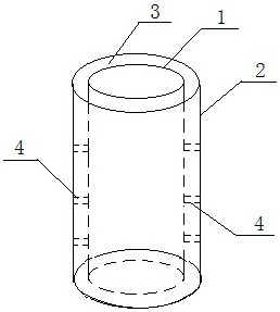
[0029] Firstly, the 3D structural diagram of the core cementation mold is drawn by the drawing software, which is in the shape of an annular cylinder. Refer to figure 1 , the core cementation mold is composed of an inner cylinder 1 and an outer cylinder 2 coaxially, the inner diameter of the inner cylinder 1 is 25mm, the outer diameter of the outer cylinder 2 is 50mm, and there are three fixing belts 4 connecting the inner cylinder 1 and the outer cylinder 2 in the annular space 3, Both ends of inner cylinder 1 are open, the upper end of annular space 3 is open, and the bottom end of annular space 3 is closed. Print the core cementation mold with ester material; fill the annular space 3 of the printed core cementation mold with dried sand par...


PUM


Abstract

The present invention relates to a cemented core mold for performance evaluation of sand-fixing formula and its experimental method, wherein the cemented core mold for performance evaluation of sand-fixing formula is prepared by the following method: draw a 3D structural diagram of the cemented core mold, the shape of which is The annular cylinder is composed of an inner cylinder and an outer cylinder coaxially. There is a fixing belt connecting the inner and outer cylinders in the annular space. Both ends of the inner cylinder are open, the upper end of the annular space is open, and the bottom end of the annular space is closed; import the 3D structure diagram into 3D In the printer, the polylactide material is used for printing; the annular space of the printed core cementation mold is filled with dried sand particles to simulate the sand bath environment, the lower port of the inner cylinder is connected with a rubber plug with holes, and waterproof glue is applied on the connection. A layer of screen mesh is pasted on the outside of the perforated rubber plug. The invention simulates the sand bath environment by filling the annular space with sand grains, and at the same time only needs to cut the soft outer wall of the mold with a knife to take out the complete cemented rock core after the rock core is cemented, avoiding damage to the cemented rock core.

Description

Technical field: [0001] The invention relates to an oil well sand control technology, in particular to a core cementation mold and an experimental method for performance evaluation of a sand consolidation formula. Background technique: [0002] Sand production in oil wells is a common problem encountered in the development of unconsolidated sandstone oilfields. Sand production in oil wells will not only cause damage to oil production tools, increase the number of pump inspections, but also cause the rock around the casing to peel off and form a deficit. Casing is deformed or even damaged, and in severe cases, the well wall will collapse, and the oil well cannot continue to produce, which will bring great harm to the safe and efficient production of the oil well. [0003] At present, oil well sand control is mainly divided into mechanical sand control and chemical sand consolidation. Compared with mechanical sand control, chemical sand consolidation can fundamentally solve th...

Claims


Application Information

Patent Timeline
Patent Type & Authority Patents(China)
IPC IPC(8): G01N1/28G01N1/36G01N3/08G01N3/20G01N15/08B33Y80/00
CPCG01N1/28G01N1/36G01N3/08G01N3/20G01N15/08B33Y80/00G01N2001/366
Inventor 冯福平刘子玉严茂森胡小康刘圣源张祯
Owner NORTHEAST GASOLINEEUM UNIV
Why Eureka
Try Eureka