Touch display panel and display device

A touch display panel and touch electrode technology, which is applied in the directions of instruments, computing, and electrical digital data processing, can solve the problems of reducing the display effect of solid-state total reflection displays and increasing the thickness of solid-state total reflection displays, so as to solve adverse effects, Achieve thin design and avoid the effect of thickness

Active Publication Date: 2019-08-30
SHANGHAI TIANMA MICRO ELECTRONICS CO LTD
View PDF5 Cites 2 Cited by
  • Summary
  • Abstract
  • Description
  • Claims
  • Application Information

AI Technical Summary

Problems solved by technology

[0003] To realize the touch function of the solid-state total reflection display, the method currently adopted is to attach a touch screen to the surface of the solid-state total reflection display panel, which will reduce the display effect of the solid-state total reflection display and increase the performance of the solid-state total reflection display. thickness

Method used


Image

  • Touch display panel and display device
  • Touch display panel and display device
  • Touch display panel and display device

Examples


Embodiment Construction

[0025] The specific implementation manners of a touch display panel and a display device provided by the embodiments of the present invention will be described in detail below with reference to the accompanying drawings. It should be noted that the described embodiments are only some of the embodiments of the present invention, but not all of the embodiments. Based on the embodiments of the present invention, all other embodiments obtained by persons of ordinary skill in the art without making creative efforts belong to the protection scope of the present invention.

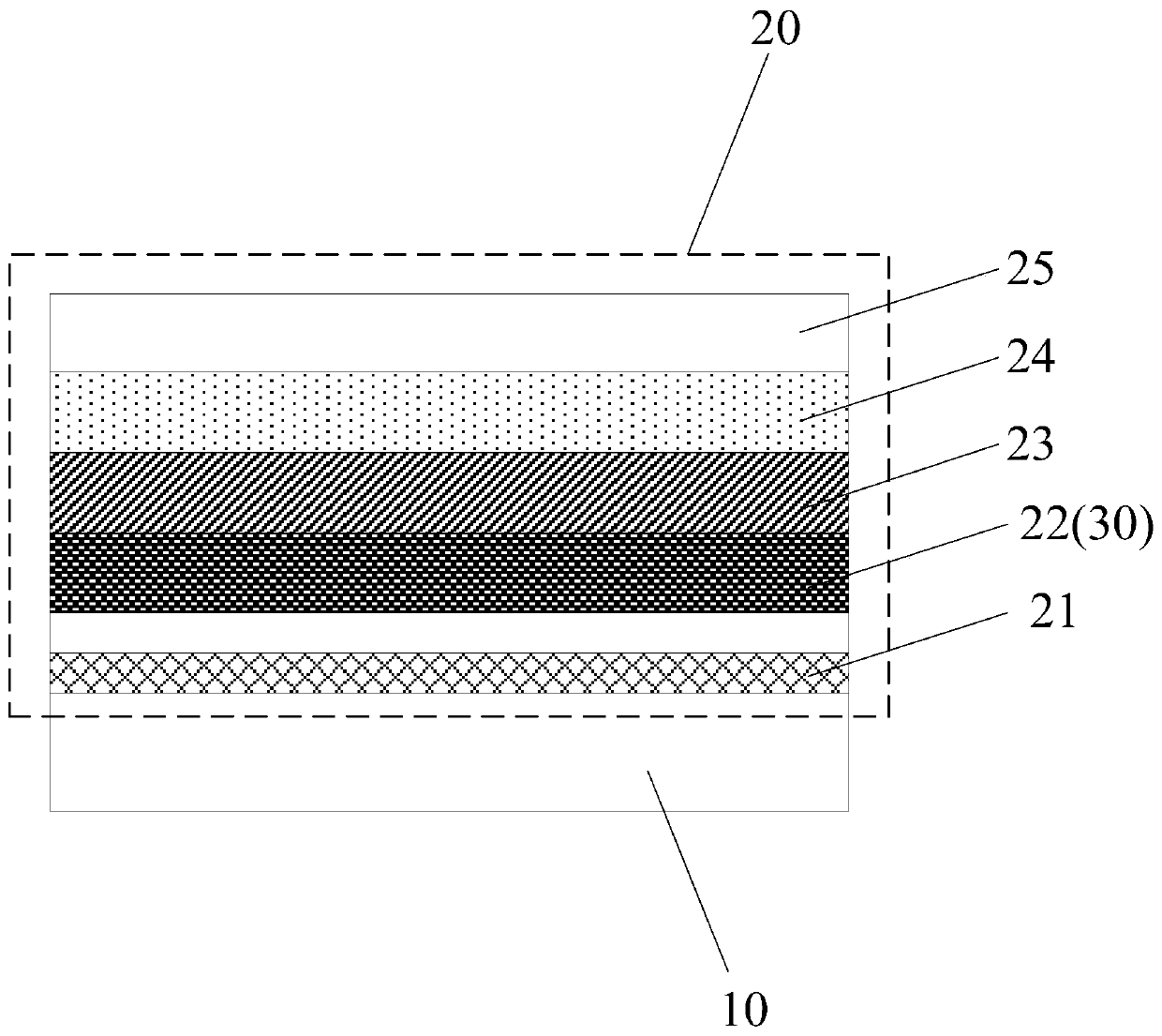
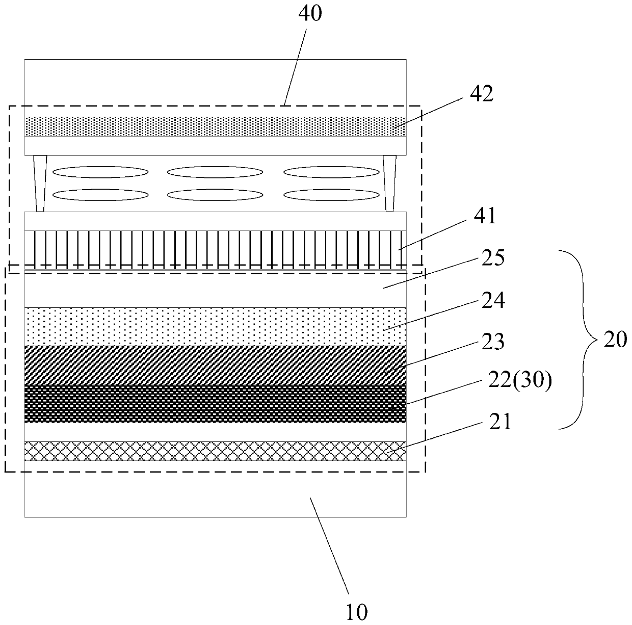
[0026] An embodiment of the present invention provides a touch display panel, such as figure 1 with figure 2 As shown, among them, figure 1 is a cross-sectional view of a touch display panel, figure 2 It is a cross-sectional view of another touch display panel.

[0027] see figure 1 with figure 2 As shown, the touch display panel may include: a base substrate 10, and a solid total reflection structure 20...


PUM


Abstract

The invention discloses a touch display panel and a display device, and relates to the technical field of display. In the embodiment of the invention, a solid total reflection structure comprises a heating structure, a reflector, a resonant structure and a phase change structure which are sequentially arranged on a substrate; the reflecting mirror serves as a touch electrode, and the touch electrode can be arranged in the solid total reflection display panel, so that the problem that the display effect is adversely affected due to the fact that the touch screen is externally hung is effectively solved, the thickness of the solid total reflection display can be prevented from being increased, and thin design is facilitated.

Description

technical field [0001] The invention relates to the field of display technology, in particular to a touch display panel and a display device. Background technique [0002] A solid-state total reflection display is a display device that is different from a liquid crystal display or an electroluminescent display. A solid-state total reflection display includes: a laminated reflective mirror, a resonant cavity, a phase-change material layer and a transparent cover layer. Among them, The reflector is used to reflect the incident light, and the material in the phase change material layer can be in a crystallized state or an amorphous state, so as to realize the switching of two colors, that is, two-color switching; by adjusting the thickness of the resonant cavity, it can The control part of the color can be reflected to the observer's side (the observer's side is generally located on the side of the transparent cover layer away from the reflector), and the other part of the colo...

Claims


Application Information

Patent Timeline
Patent Type & Authority Applications(China)
IPC IPC(8): G06F3/041G06F3/044
CPCG06F3/0412G06F3/044G06F2203/04103
Inventor 卢峰
Owner SHANGHAI TIANMA MICRO ELECTRONICS CO LTD
Why Eureka
Try Eureka