Flatness detection method, device, equipment, storage medium and system
A detection method and flatness technology, applied in the direction of measuring devices, optical devices, image analysis, etc., can solve the problems of high cost, low accuracy, slow flatness detection speed, etc., to speed up detection speed, ensure accuracy, The effect of reducing detection complexity and detection cost
- Summary
- Abstract
- Description
- Claims
- Application Information
AI Technical Summary
Problems solved by technology
Method used
Image
Examples
Embodiment 1
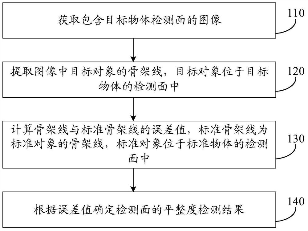
[0079] figure 1 It is a flow chart of a flatness detection method provided in Embodiment 1 of the present invention. The flatness detection method provided in the embodiment can be executed by a flatness detection device, which can be realized by software and / or hardware, and the flatness detection device can be composed of two or more physical entities, or Can be a physical entity. For example, the flatness detection equipment can be a mobile phone, an industrial control computer, etc. In the embodiment, an industrial control computer is used as an example to describe the flatness detection device.
[0080] Optionally, the flatness detection device can be used as an independent device to directly acquire externally input image data for processing. Alternatively, the flatness detection device can also be integrated in the flatness detection system. At this time, the flatness detection device can obtain and process data obtained by other data acquisition devices in the flatn...
Embodiment 2
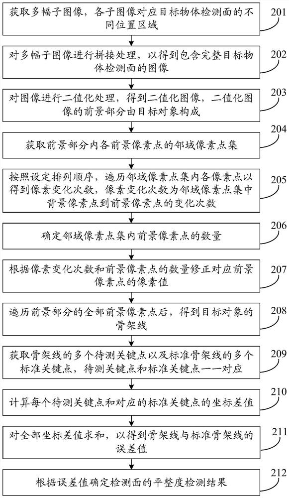
[0099] figure 2 It is a flow chart of a flatness detection method provided by Embodiment 2 of the present invention. This embodiment is embodied on the basis of the above-mentioned embodiments.
[0100] In this embodiment, the target object is a keyboard keycap, the detection surface is a plane on which characters are printed on the keycap, and the target object is a character.
[0101] Specifically, the target object is a keyboard keycap, which may be a specific keycap, several specific keycaps or all keycaps in the keyboard. In the embodiment, it is described that the target objects are all keycaps in the keyboard as an example. Further, the detection surface is a plane on which characters are printed in the keycap, that is, a user touch surface. Wherein, characters such as letters, numbers and / or symbols are printed on the detection surface of each key cap, and in the embodiment, the characters printed on the key cap are used as the target object of the key cap.
[010...
Embodiment 3
[0183] Figure 8 It is a schematic structural diagram of a flatness detection device provided in Embodiment 3 of the present invention. refer to Figure 8 , the flatness detection device includes: an image acquisition module 501 , a skeleton line extraction module 502 , an error value calculation module 503 and a result determination module 504 .
[0184] Wherein, the image acquisition module 501 is used to acquire an image comprising the detection surface of the target object; the skeleton line extraction module 502 is used to extract the skeleton line of the target object in the image, and the target object is located in the detection surface of the target object; the error value calculation module 503 , used to calculate the error value between the skeleton line and the standard skeleton line, the standard skeleton line is the skeleton line of the standard object, and the standard object is located in the detection surface of the standard object; the result determination m...
PUM
 Abstract
Description
Claims
Application Information
 - R&D
- Intellectual Property
- Life Sciences
- Materials
- Tech Scout
- Unparalleled Data Quality
- Higher Quality Content
- 60% Fewer Hallucinations
Browse by: Latest US Patents, China's latest patents, Technical Efficacy Thesaurus, Application Domain, Technology Topic, Popular Technical Reports.
© 2025 PatSnap. All rights reserved.Legal|Privacy policy|Modern Slavery Act Transparency Statement|Sitemap|About US| Contact US: help@patsnap.com


