Gate valve convenient to regulate and control

A plug-in valve, valve body technology, applied in the direction of sliding valve, valve details, valve device, etc., can solve the problem of unclear opening and closing degree of valve plate, inability to understand the opening and closing degree of valve plate from the remote end, etc., and achieve intuitive opening and closing. The effect of closing degree and convenient adjustment

Pending Publication Date: 2019-09-03
ZHENGZHOU JINCHENG CHENGXIN SCREEN EQUIP CO LTD
View PDF0 Cites 1 Cited by
  • Summary
  • Abstract
  • Description
  • Claims
  • Application Information

AI Technical Summary

Problems solved by technology

The invention can intuitively understand the degree of opening and closing of the valve plate, so as to make it more convenient to adjust. The bevel gear 2 is arranged on the screw rod, and the screw rod is provided with an angular displacement sensor through a coupling, which solves the problem of the existing plug-in plate. The valve is not clear about the opening and closing degree of the valve plate, and it is impossible to know the opening and closing degree of the valve plate from the remote end

Method used


Image

  • Gate valve convenient to regulate and control
  • Gate valve convenient to regulate and control
  • Gate valve convenient to regulate and control

Examples


Embodiment 1

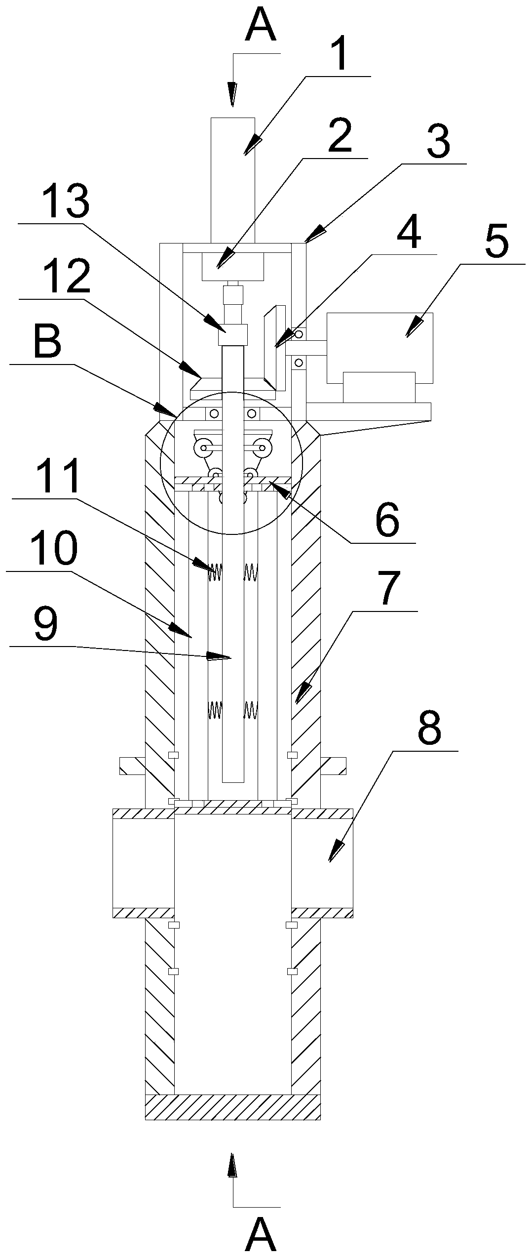
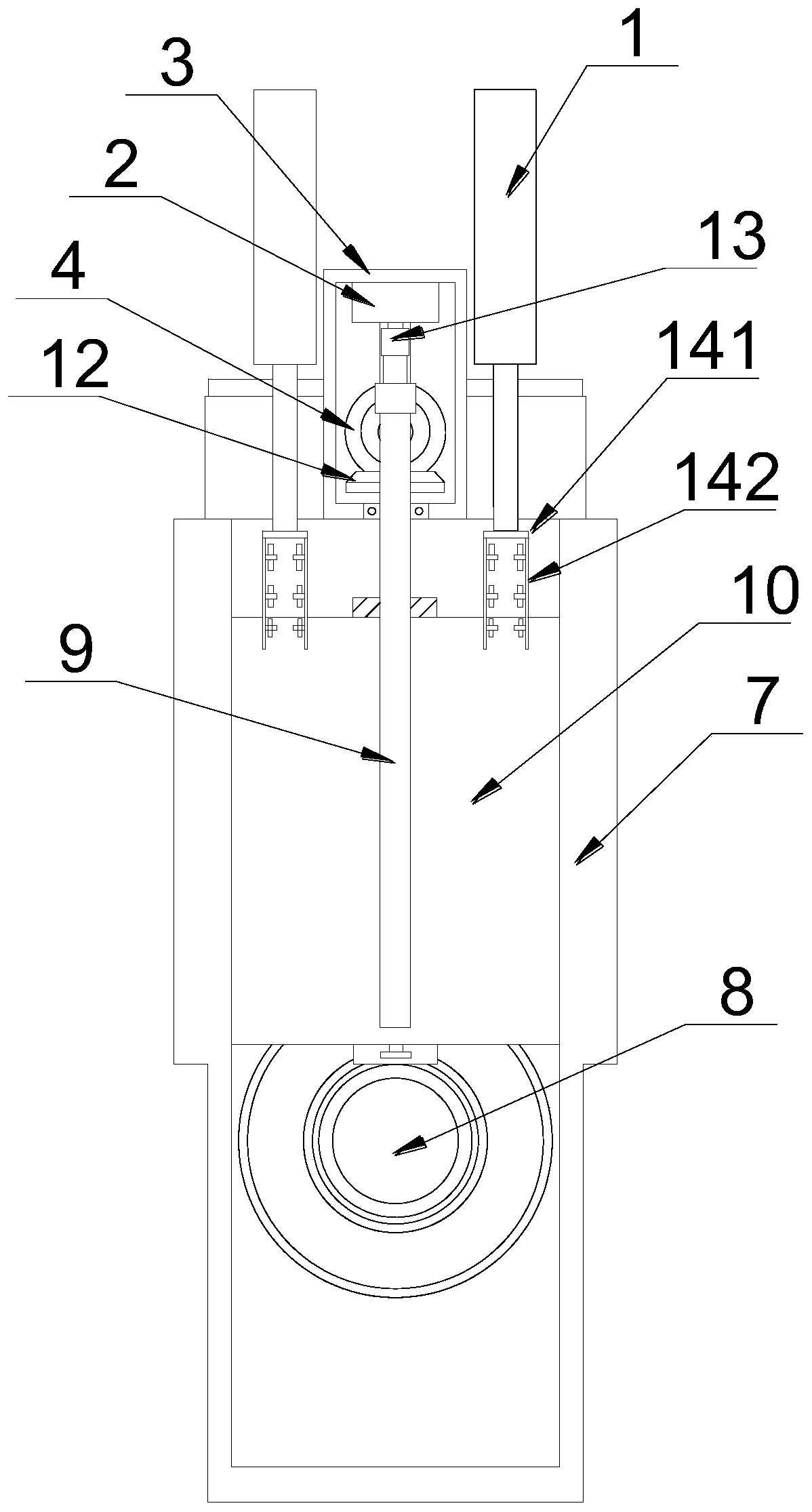
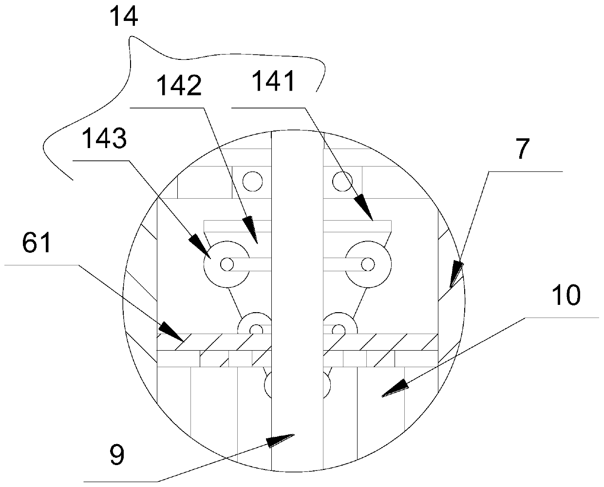
[0030] see Figure 1~3 , a plug-in valve that is easy to control, including a valve body 7, a through hole 8 is opened on the valve body 7, a valve plate 10 is arranged in the valve body 7, and a valve body 7 is provided with a transmission connection with the valve body 7 at the upper end of the valve body 7 Drive mechanism one, described drive mechanism one comprises the motor 5 that is positioned at the upper end of valve body 7 and is arranged laterally, and the output end of described motor 5 is provided with bevel gear-4, and described bevel gear-4 is meshed with can be wound around the vertical shaft Rotating bevel gear 2 12, said bevel gear 2 12 is fixedly sleeved with a screw 9, the lower end of the screw 9 extends into the valve body 7 and is threadedly connected with a transmission member 6, and the transmission member 6 is fixed to the valve plate 10 Connected, the upper end of the screw rod 9 extends out of the bevel gear 2 12 and is provided with a coupling 13, t...

Embodiment 2

[0034] see Figure 1~3, a plug-in valve that is easy to control, including a valve body 7, a through hole 8 is opened on the valve body 7, a valve plate 10 is arranged in the valve body 7, and a valve body 7 is provided with a transmission connection with the valve body 7 at the upper end of the valve body 7 Drive mechanism one, described drive mechanism one comprises the motor 5 that is positioned at the upper end of valve body 7 and is arranged laterally, and the output end of described motor 5 is provided with bevel gear-4, and described bevel gear-4 is meshed with can be wound around the vertical shaft Rotating bevel gear 2 12, said bevel gear 2 12 is fixedly sleeved with a screw 9, the lower end of the screw 9 extends into the valve body 7 and is threadedly connected with a transmission member 6, and the transmission member 6 is fixed to the valve plate 10 Connected, the upper end of the screw rod 9 extends out of the bevel gear 2 12 and is provided with a coupling 13, th...


PUM


Abstract

The invention relates to the technical field of valves, and discloses a gate valve convenient to regulate and control. The gate valve comprises a valve body, a through hole is formed in the valve body, a valve plate is arranged in the valve body, a first driving mechanism in transmission connection with the valve body is arranged at the upper end of the valve body, the first driving mechanism comprises a motor located at the upper end of the valve body and arranged transversely, the output end of the motor is sleeved with a first bevel gear, the first bevel gear is provided with a second bevelgear capable of rotating around the vertical axis in a meshed manner, and a screw is fixedly sleeved with the second bevel gear; and the lower end of the screw extends into the valve body and is in threaded connection with a transmission member, the transmission member is fixedly connected with the valve plate, the upper end of the screw extends out of the second bevel gear and is provided with acoupling, the upper end of the coupling is in transmission connection with an angular displacement sensor, the angular displacement sensor is provided with a fixing frame, and the signal output end of the angular displacement sensor is electrically connected to a valve control system. The gate valve can realize the intuitive understanding of the opening and closing degree of the valve plate, andadjustment is more convenient to achieve.

Description

technical field [0001] The invention relates to the technical field of valves, in particular to a plug-in valve that is easy to regulate. Background technique [0002] The flapper valve is also called the manual knife gate valve. The knife gate valve is a valve in which the gate and the valve seat are always in close contact and sealed. Make the round opening on the ram board completely disengage and coincide with the diameter. The advantage of this valve is that there is no groove in the bore of the valve body, the medium will not be blocked and blocked, and it has full-bore flow characteristics. Its sealing structure can be divided into soft seal and hard seal structure. [0003] The existing flapper valve mainly uses the driving parts to drive the valve plate to move up and down to achieve the opening and closing effect. The opening and closing degree of the valve plate cannot be precisely controlled, and some mechanical limit switches not only increase the work difficul...

Claims


Application Information

Patent Timeline
Patent Type & Authority Applications(China)
IPC IPC(8): F16K3/16F16K3/316F16K31/04F16K31/122F16K31/53F16K37/00
CPCF16K3/16F16K3/3165F16K31/043F16K31/122F16K31/53F16K37/0083
Inventor 李媛媛
Owner ZHENGZHOU JINCHENG CHENGXIN SCREEN EQUIP CO LTD
Why Eureka
Try Eureka