
Synchronous rectification circuit and rectifying device

A rectification circuit and synchronous rectification technology, applied in the electronic field, can solve the problems of occupation, multi-PCB space, increasing the difficulty and cost of transformer winding, etc.

Active Publication Date: 2019-09-03
SHINRY TECH
View PDF6 Cites 0 Cited by
  • Summary
  • Abstract
  • Description
  • Claims
  • Application Information

AI Technical Summary

Problems solved by technology

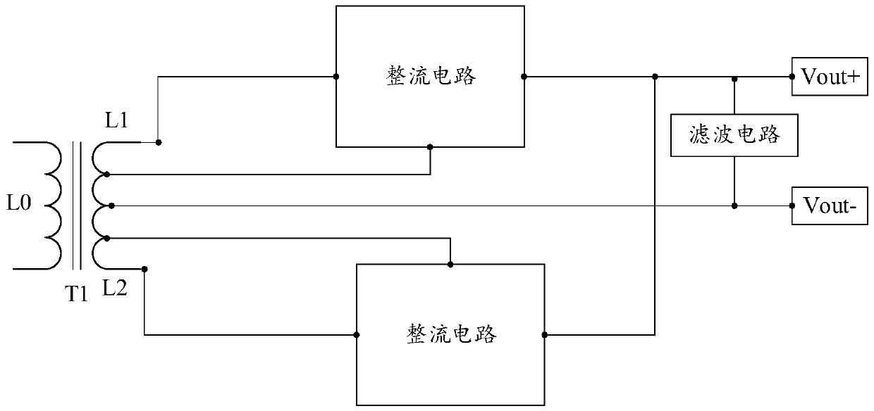
The conventional power supply method is to add an additional power supply winding to the transformer to supply power to the rectifier circuit, and the circuit is often complicated, which increases the difficulty and cost of transformer winding
And when laying out the board on the printed circuit board (Printed Circuit Board, PCB), it needs to occupy more PCB space, which is not conducive to improving the power density of the power supply

Method used


Image

  • Synchronous rectification circuit and rectifying device
  • Synchronous rectification circuit and rectifying device
  • Synchronous rectification circuit and rectifying device

Examples


Embodiment Construction

[0027] In order to enable those skilled in the art to better understand the solution of the present application, the technical solution in the embodiment of the application will be clearly and completely described below in conjunction with the accompanying drawings in the embodiment of the application. Obviously, the described embodiment is only It is a part of the embodiments of this application, not all of them. Based on the embodiments in this application, all other embodiments obtained by persons of ordinary skill in the art without creative efforts fall within the protection scope of this application.

[0028] The terms "first", "second" and the like in the specification and claims of the present application and the above drawings are used to distinguish different objects, rather than to describe a specific order. Furthermore, the terms "include" and "have", as well as any variations thereof, are intended to cover a non-exclusive inclusion. For example, a process, system...


PUM


Abstract

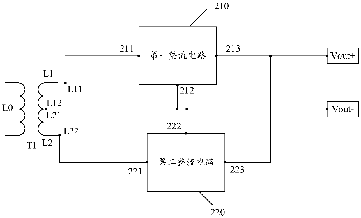
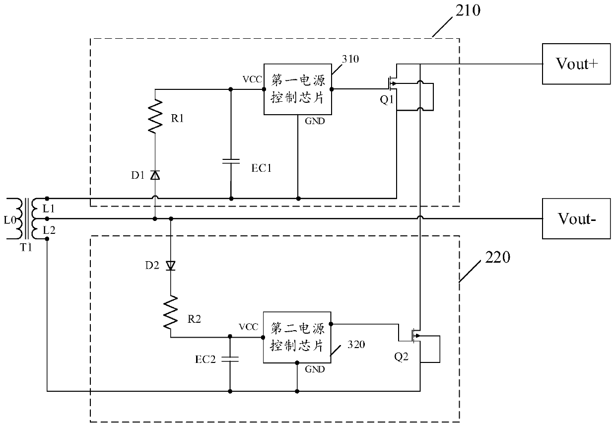
A synchronous rectification circuit and a rectifying device, the synchronous rectification circuit comprising a transformer (T1), a first rectification circuit (210), a second rectification circuit (220), a power supply output positive terminal (Vout+), and a power supply output negative terminal (Vout-) Wherein: said transformer (T1) comprises a primary winding (LO), a first secondary winding (L1) and a second secondary winding (L2); a first end of said first secondary winding (L1) is connected to the first input end (211) of the first rectifier circuit (210), and the second end (L12) of thefirst secondary winding (L1) is connected to the first rectifier circuit (210) a second input terminal (212), a second input terminal (222) of the second rectifier circuit (220), a first terminal (L21) of the second secondary winding (L2), and a negative end of the power supply output ( a second end (L22) of the second secondary winding (L2) is connected to the first input end (221) of the secondrectifier circuit (220); the first rectifier circuit (210) The output end (213) is connected to the output end (223) of the second rectifying circuit (220) and the power output positive end (Vout-); no additional power supply winding is required on the transformer (T1) to reduce transformer processing Cost, more conducive to PCB wiring Power density increase.

Description

technical field [0001] The present application relates to the field of electronic technology, in particular to a synchronous rectification circuit and a rectification device. Background technique [0002] A rectifying circuit is a circuit that converts AC power into DC power. Most rectification circuits are composed of transformers, rectification main circuits and filters. It is widely used in the fields of DC motor speed regulation, generator excitation regulation, electrolysis, electroplating and other fields. A rectifier circuit usually consists of a main circuit, a filter and a transformer. [0003] In the application of the rectification circuit, the synchronous rectification circuit is a relatively preferred circuit, such as figure 1 shown. Its conventional power supply method is to add an additional power supply winding to the transformer to supply power to the rectifier circuit, and the circuit is often complicated, which increases the difficulty and cost of tran...

Claims


Application Information

Patent Timeline
IPC IPC(8): H02M7/217
CPCH02M7/217
Inventor 赵德琦赵武吴壬华
Owner SHINRY TECH
Features
  • Generate Ideas
  • Intellectual Property
  • Life Sciences
  • Materials
  • Tech Scout
  • Unparalleled Data Quality
  • Higher Quality Content
  • 60% Fewer Hallucinations
Learn More