Device for cleaning dialysate liquid storage barrels

A cleaning device and liquid storage tank technology, applied in the field of medical machinery, can solve the problems of high impact force of pure water and inability to ensure the cleaning of the inside of the tank, and achieve the effects of easy removal, strong cleaning effect, and simple and convenient equipment operation

Pending Publication Date: 2019-09-06
TIANJIN RUIPENG MEDICAL DEVICES
View PDF0 Cites 0 Cited by
  • Summary
  • Abstract
  • Description
  • Claims
  • Application Information

AI Technical Summary

Problems solved by technology

[0003] After the medicine liquid storage barrel is completed by plastic blow molding, since the inside of the barrel cannot be guaranteed to be clean, including the process of transportation and storage, it may be polluted, and the cleanliness of the medicine is very high. Therefore, when the medicine liquid storage barrel is filled Before filling, it is necessary to clean the inside of the medicine liquid storage barrel by spraying pure water before filling it. During the cleaning process, the medicine liquid storage barrel is turned upside down and inserted into the cleaning nozzle. People turn on the water pump through the switch, and the water pump pumps the pure water Pump it into the cleaning nozzle, and spray pure water through the cleaning nozzle to clean the drug storage tank. However, in order to improve the cleaning effect, the sprayed pure water has a greater impact, and the plastic drug storage tank is lighter. Therefore, it is necessary to press the drug liquid storage barrel during the reinstallation process, which makes the process of installing the drug liquid storage barrel upside down very troublesome, and increases the probability of secondary pollution caused by the dropping of the pressing device or the dirt on people's hands

Method used


Image

  • Device for cleaning dialysate liquid storage barrels
  • Device for cleaning dialysate liquid storage barrels
  • Device for cleaning dialysate liquid storage barrels

Examples


Embodiment Construction

[0032] The present invention will be described in further detail below in conjunction with the accompanying drawings.

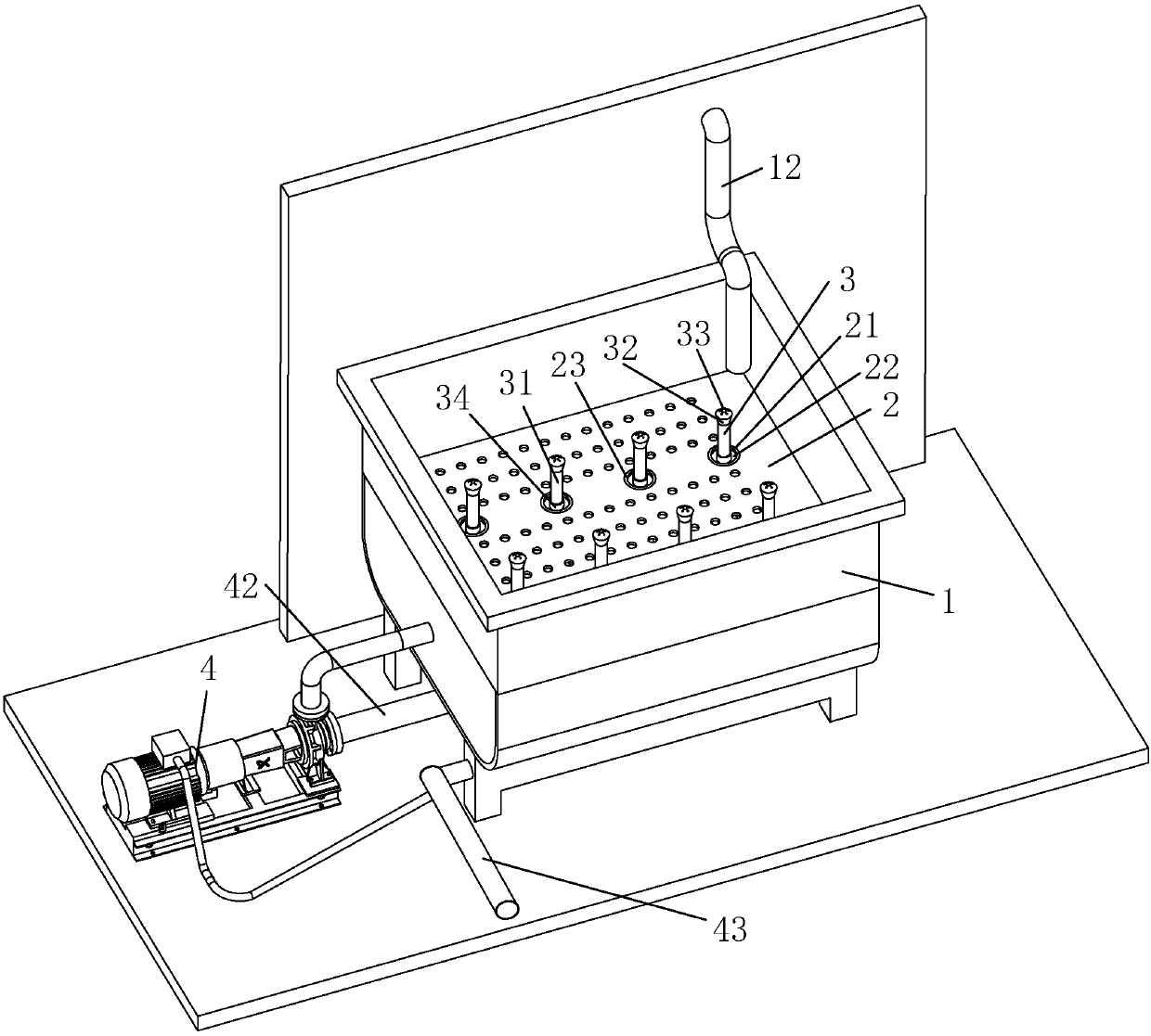
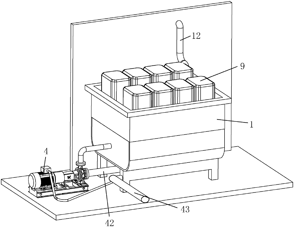
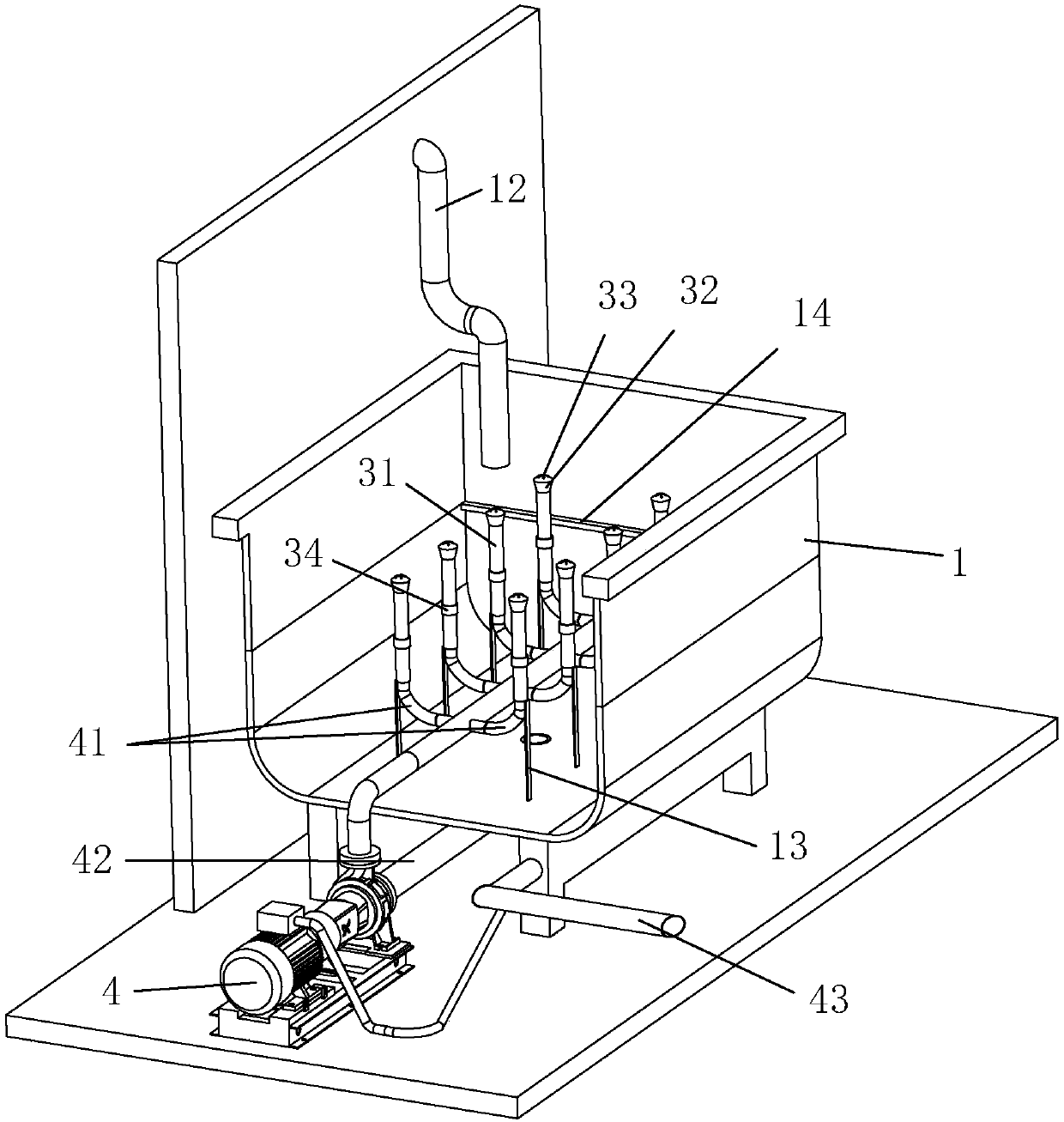
[0033] A dialysate storage tank cleaning device, such as figure 1 , 2 As shown, it includes a cleaning box 1, a water leakage baffle 2, a cleaning nozzle 3, and a water pump 4 for supplying water to the cleaning nozzle 3. The bottom of the cleaning box 1 is provided with a drain valve 11, and the cleaning nozzle 3 is vertically fixed at the bottom of the cleaning box 1. , the inner edge of the cleaning box 1 is provided with a supporting rib 14, and the edge of the leaking baffle 2 is in contact with the supporting rib 14, and the leaking baffle 2 is provided with a fixing hole 21 protruding for the cleaning nozzle 3, and the fixing hole 21 and the cleaning There is a gap 22 between the nozzles 3 for inserting the barrel tube 91 of the drug liquid storage barrel 9. People align the barrel tube 91 of the drug liquid storage barrel 9 with the cleaning nozzle 3...


PUM


Abstract

The invention discloses a device for cleaning a dialysate liquid storage barrel, and belongs to the field of medical machinery. The device has the advantage of facilitating fixed cleaning of drug liquid storage barrels. According to the technical scheme, the device comprises a cleaning tank, a water leakage baffle, cleaning spray heads and a water pump for supplying water to the cleaning spray heads, the bottom of the cleaning tank is provided with a drainage valve, the cleaning spray heads are vertically fixed at the bottom end inside the cleaning tank, the water leakage baffle is transversely arranged inside the cleaning tank, the water leakage baffle is provided with fixing holes from which the cleaning spray heads extend out, a gap for inserting a barrel pipe of each drug liquid storage barrel is arranged between the corresponding fixing hole and the corresponding cleaning spray head, the bottom of each cleaning spray head is fixedly connected to the bottom end inside the cleaningtank through an elastic column, the water pump is provided with water outlet hoses, each water outlet hose is connected to the corresponding cleaning spray head, and each water outlet hose is arrangedat the position of the corresponding elastic column in a bent mode.

Description

technical field [0001] The invention relates to the field of medical machinery, in particular to a device for cleaning a dialysis fluid storage tank. Background technique [0002] Medicines play a vital role in medical assistance. Medicines include liquid medicines, solid medicines, etc. Liquid medicines need to be stored in bottles and liquid storage barrels, such as syrup, which are basically stored in bottles, such as dialysate. Use makes the demand large, and is generally stored in the drug storage tank. [0003] After the medicine liquid storage barrel is completed by plastic blow molding, since the inside of the barrel cannot be guaranteed to be clean, including the process of transportation and storage, it may be polluted, and the cleanliness of the medicine is very high. Therefore, when the medicine liquid storage barrel is filled Before filling, it is necessary to clean the inside of the medicine liquid storage barrel by spraying pure water before filling it. Durin...

Claims


Application Information

Patent Timeline
IPC IPC(8): B08B9/28B08B13/00
CPCB08B9/28B08B13/00
Inventor 甄莉莉王宁甄军
Owner TIANJIN RUIPENG MEDICAL DEVICES
Why Eureka
Try Eureka