Tiny ink dot thermal bubble inkjet detection equipment used based on printer

A technology for detecting equipment and hot air bubbles, which is applied in printing and other directions, can solve the problems of affecting line thickness, increasing printing blur, and increasing inkjet strength, etc., to achieve the effect of improving singleness, improving clarity, and stabilizing the state of droplets

Inactive Publication Date: 2019-09-06
黄春燕
View PDF5 Cites 0 Cited by
  • Summary
  • Abstract
  • Description
  • Claims
  • Application Information

AI Technical Summary

Problems solved by technology

[0004] Aiming at the deficiencies in the prior art, the purpose of the present invention is to provide a thermal bubble inkjet detection device based on tiny ink dots used by the printer to solve the problem that the capillary of the thermal bubble jet is a small needle and has a slideway groove change track. Ink effect, let the ink dots appear on the paper drop by drop. In the thermal bubble processing ink, the process of heating, expansion and compression will make the ink with calorific value flow into the capillary to expand the air quality, so that the needle opening will gradually The operation of thermal bubble inkjet expands into bifurcated ink dots during inkjet, which interferes with the accuracy of inkjet drawing, and the capillary tube is more difficult to compress the ink. Insufficient, the opening inkjet gradually overflows from small ink droplets to large ink droplets, intuitively aggravating the inkjet force, affecting the thickness of the printed lines after printing, and increasing the printing blur

Method used


Image

  • Tiny ink dot thermal bubble inkjet detection equipment used based on printer
  • Tiny ink dot thermal bubble inkjet detection equipment used based on printer
  • Tiny ink dot thermal bubble inkjet detection equipment used based on printer

Examples


Embodiment Construction

[0031] In order to make the technical means, creative features, goals and effects achieved by the present invention easy to understand, the present invention will be further described below in conjunction with specific embodiments.

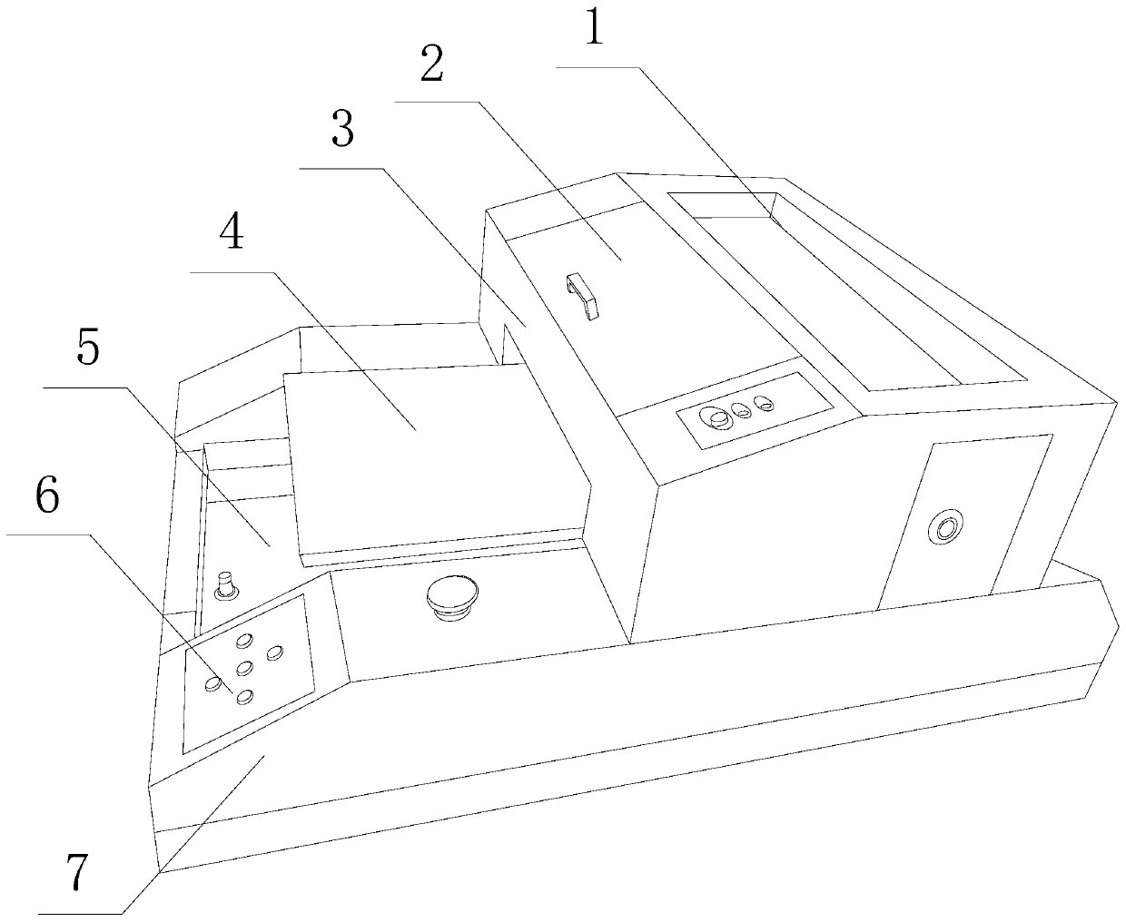
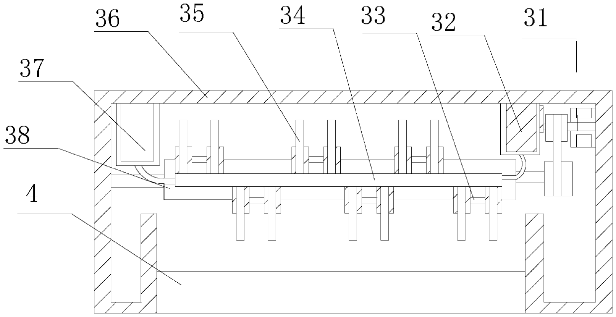
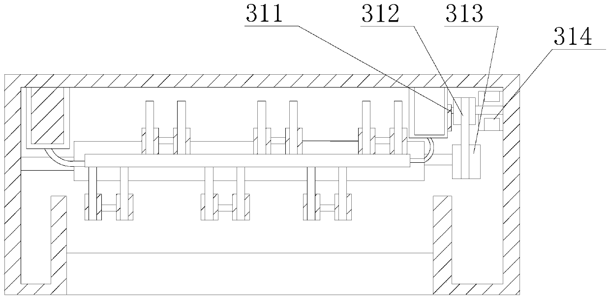
[0032] see Figure 1-Figure 8 , the present invention provides a micro-dot thermal bubble jet detection device based on a printer, and its structure includes: a storage tank 1, a flip cover plate 2, a thermal bubble jet box 3, a printing platform 4, a screw advance slot 5, a button The control board 6 and the power distribution base 7, the bottom of the screw propulsion groove 5 is nested into the groove of the power distribution base 7, and the wire at the bottom of the button control board 6 is integrated with the power distribution base 7 The board is electrically connected, the bottom shaft wheel of the printing platform 4 is mechanically connected with the screw rod of the screw screw propulsion groove 5, and the thermal bubble jet box 3 is nes...


PUM


Abstract

The invention discloses tiny ink dot thermal bubble inkjet detection equipment used based on a printer. The equipment structurally comprises a placing groove, a turnover cover plate, a thermal bubbleinkjet box, a printing table base, a lead screw propelling groove, a button control plate and a power distribution base. The thermal bubble inkjet box and the printing table base are matched, a capillary needle tube and a cold barrel deflection mechanism slide to form a surrounding effect of a small cold tube on heated ink, the ink can be cooled on the wall of the capillary needle tube from the end introducing thermal expanded ink to a tip end of the thin tube to be output, the drop state of inkjet of a protective needle head is stable, it is ensured that the inner temperature expansion forceof the thin tube is controlled to be matched with the compression to be output on the printing table base, the correction effect on a fine adjustment offset needle head is formed through a deflectiondisc seat bridged in the middle, small ink drops formed by thermal bubbles can be accurately sprayed on printing paper, small ink drops formed by thermal bubbles can be accurately ejected to printingpaper, lines of the printing effect can be clearly adjusted to be single-line or double-line composite ink-jet effects, the unicity of the ink-jet state is improved, and the definition of accurate distribution of the lines is also improved.

Description

technical field [0001] The invention relates to a tiny ink dot thermal bubble inkjet detection device used by a printer, which belongs to the field of ink cartridges. Background technique [0002] Inkjet printers are common paint spraying and black-and-white spraying effects. It has an intuitive and elegant printing method for the printed color blocks. It is more direct than powder printing, avoiding the printing of powder, and the ink paint has a longer adhesion time and improves brightness. It has a good effect on extending the service life of long-term printing files. The shortcomings of the current technology that need to be optimized are: [0003] The capillary of thermal bubble inkjet is a small needle, and the inkjet effect with the changing track of the slide groove makes the ink dots appear on the paper drop by drop. In the ink processed by thermal bubble processing, the process of heating, expansion and compression will Let the ink with heat value flow into the ca...

Claims


Application Information

Patent Timeline
Patent Type & Authority Applications(China)
IPC IPC(8): B41J2/01B41J2/175
CPCB41J2/01B41J2/175
Inventor 黄春燕
Owner 黄春燕
Why Eureka
Try Eureka