[0032] The technical solutions of the present invention will be clearly and completely described below in conjunction with the accompanying drawings. Obviously, the described embodiments are part of the embodiments of the present invention, rather than all of them. Based on the embodiments of the present invention, all other embodiments obtained by those of ordinary skill in the art without creative work shall fall within the protection scope of the present invention.
[0033] In the description of the present invention, it should be noted that the terms "center", "upper", "lower", "left", "right", "vertical", "horizontal", "inner", "outer", etc. The indicated orientation or positional relationship is based on the orientation or positional relationship shown in the drawings, and is only for the convenience of describing the present invention and simplifying the description, rather than indicating or implying that the pointed device or element must have a specific orientation or a specific orientation. The structure and operation cannot therefore be understood as a limitation of the present invention. In addition, the terms "first", "second", "third", etc. are only used for descriptive purposes, and cannot be understood as indicating or implying relative importance.
[0034] In the description of the present invention, it should be noted that the terms "installation", "connected" and "connected" should be understood in a broad sense, unless otherwise clearly specified and limited. For example, they can be fixed or detachable. Connected or integrally connected; it can be a mechanical connection or an electrical connection; it can be directly connected or indirectly connected through an intermediate medium, and it can be the internal communication between two components. For those of ordinary skill in the art, the specific meaning of the above-mentioned terms in the present invention can be understood in specific situations.
[0035] Such as figure 1 with figure 2 As shown, the underwater propeller provided by the present invention includes: a housing 100, a drive assembly 200, a drive shaft 300, a first impeller 400 and a second impeller 500.
[0036] The housing 100 is arranged in a cylindrical shape, the front end (upstream position) and the rear end (downstream position) of the housing 100 are both set in a tapered shape, and the housing 100 is provided with a fluid channel 110 and an accommodation cavity 120; the fluid channel 110 is used for Through water flow, the fluid channel 110 includes a water inlet 111 and a water outlet 112; preferably, the water inlet 111 is provided at the bottom of the housing 100, and the water outlet 112 is provided at one end of the housing 100 in the axial direction;
[0037] A pressurizing zone 113 is provided in the fluid channel 110 close to the drain port 112. The inner diameter of the pressurizing zone 113 decreases along the drainage direction. Since the inner diameter of the pressurizing zone 113 decreases, it can increase the pressure of the water flow. Then increase the flow rate;
[0038] The drive shaft 300 is arranged inside the housing 100 and is connected to the drive assembly 200;
[0039] The driving assembly 200 is arranged in the accommodating cavity 120 for driving the driving shaft 300 to rotate;
[0040] The first impeller 400 is fixedly connected to the drive shaft 300 and can rotate synchronously with the drive shaft 300, and the second impeller 500 can be rotatably connected to the drive shaft 300 to rectify the water flow discharged from the first impeller 400; and, The first impeller 400 is located upstream of the second impeller 500, and the second impeller 500 is located inside the pressurizing zone 113.
[0041] In the underwater propeller of the present application, since the fluid channel 110 in the housing 100 is provided with a pressurizing area 113 at a position close to the drain port 112, the inner diameter of the pressurizing area 113 decreases along the drainage direction; the second impeller 500 is located at the pressurizing Inside the zone 113, the first impeller 400 is located upstream of the second impeller 500. When the drive assembly 200 drives the first impeller 400 to rotate through the drive shaft 300, the first impeller 400 pushes the water flow into the pressurization zone 113. The inner diameter of 113 decreases along the drainage direction; the second impeller 500 located in the pressurization zone 113 accelerates the water flow and sprays it out of the drainage port 112, thereby increasing the propulsion force, increasing the propulsion power of the underwater propeller and improving the driving effect. It can be installed separately to realize miniaturization and modularization.
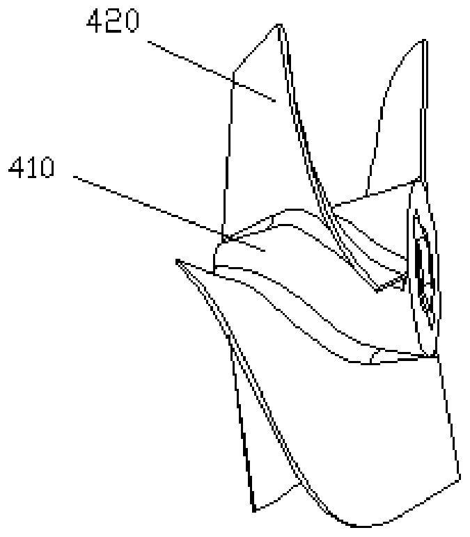
[0042] In the preferred embodiment of this application, refer to image 3 , The first impeller 400 includes a first hub 410 and a plurality of spiral-shaped first blades 420 connected to the circumferential side of the first hub 410; the first hub 410 is tapered, and the diameter of the first hub 410 is The direction of drainage increases.
[0043] In this embodiment, since the diameter of the first hub 410 increases along the drainage direction, the resistance to the water flow is effectively reduced during the traveling process; the first blades 420 are arranged in a spiral shape, and the plurality of first blades 420 react to the fluid. Work is performed to accelerate the water flow and spray it backwards. In addition to the backward movement of the fluid passing through the first impeller 400, there is also harmful movement relative to the axis of the drive shaft 300, in order to eliminate the aforementioned harmful rotation movement. In the technical solution of the present application, a second impeller 500 is provided downstream of the first impeller 400, which plays a role of rectifying, so that all the rotational motion of the fluid is converted into backward motion, thereby increasing the driving force of the water flow.
[0044] In the preferred embodiment of this application, refer to Figure 4 The above-mentioned second impeller 500 includes a second hub 510 and a plurality of second blades 520 connected to the peripheral side of the second hub 510. The second hub 510 is sleeved on the drive shaft 300 through a bearing, and the second blade The hub 510 is tapered, and the diameter of the second hub 510 decreases in the drainage direction.
[0045] In this embodiment, since the second hub 510 is tapered, the diameter of the second hub 510 decreases in the drainage direction. When assembling, the diameter of the abutting end of the first hub 410 and the second hub 510 is required to match. So in the process of traveling, it can effectively reduce the resistance to the water flow.
[0046] Preferably, the second blade 520 includes a first bending portion 521 and a second bending portion 522 that are sequentially connected in the drainage direction, and a certain angle is set between the first bending portion 521 and the second bending portion 522. The length of the second bending portion 522 is greater than the length of the first bending portion 521, the second bending portion 522 extends along the axial direction of the second hub 510, and the first bending portion 521 and the second bending portion 522 are opposite to each other. Used in combination, it can adjust the flow direction of the fluid, so that all the rotational motion of the fluid is converted into backward motion, thereby increasing the driving force of the water flow; and because the diameter of the pressurization zone 113 where the second impeller 500 is located is along the water flow direction Therefore, under the combined action of the second impeller 500 and the pressurization zone 113, the water flow is pressurized and rectified, and then sprayed out through the drain port 112, thereby greatly increasing the driving force of the propeller.
[0047] In a preferred embodiment of the present application, the drive assembly 200 includes a controller 210, a motor 220, a reducer 230, and a sealed housing 240; the controller 210 is electrically connected to the motor 220, and is used to control the opening, closing and output power of the motor 220. 220 is connected to the input end of the reducer 230, the output end of the reducer 230 is connected to the drive shaft 300, and the sealed housing 240 is located at the output end of the reducer 230 and is fixed in the housing 100. Multiple seals (not shown in the figure) need to be provided between the sealed housing 240 and the inner wall of the housing 100 to prevent water flow from entering the accommodating cavity 120; the aforementioned reducer 230 uses a planetary gear reducer 230 for To adjust the speed of the drive shaft 300, the motor 220 is connected to the input end of the reducer 230 through a coupling. The end of the drive shaft 300 penetrates the sealed housing 240 and extends into the reducer, and is connected to the output end of the reducer 230.
[0048] Preferably, refer to figure 1 The end of the aforementioned sealed housing 240 close to the drain 112 is the diversion portion 241, and the diversion portion 241 is in the shape of a cone, and the diameter of the diversion portion 241 decreases along the drainage direction. During the application process, since a part of the sealed housing 240 is at the position of the water inlet 111, it will generate resistance to the water flow. In this embodiment, the guide portion 241 is set in a cone shape to introduce the water flow to the drive shaft 300 The axial direction plays a role of drainage.
[0049] Preferably, a sealing element 250 is provided between the sealed housing 240 and the drive shaft 300, and at the same time, a sealing element 250 is provided between the output end of the reducer 230 and the drive shaft 300. The above-mentioned sealing element 250 may adopt an oil seal or a water seal, or a combination of an oil seal and a water seal. For example, in this embodiment, an oil seal and a water seal are respectively provided between the sealed housing 240 and the drive shaft 300, wherein the water seal is provided near the rear side. An oil seal is provided between the output end of the reducer 230 and the output shaft. The use of the above-mentioned sealing element 250 can ensure the airtightness of the motor 220, the reducer 230, and the accommodating cavity 120.
[0050] The underwater propulsion provided in this application can use various methods to supply power to the control and motor 220. For details, refer to the following description.
[0051] The first charging method
[0052] In a preferred embodiment of the present application, the underwater propeller further includes a first charging assembly 600, the first charging assembly 600 includes a first connecting body 610, one end of the first connecting body 610 is connected with a cable 700, and the other end is connected with the controller 210 An electrical connection in the form of a plug and a jack is adopted to supply power to the controller 210 and the motor 220. For example, it should be noted that the plug can be provided on the controller 210 or the first connector 610. Correspondingly, the jack can be provided on the controller 210 or the first connector 610. on. The cable 700 functions to connect an external power source.
[0053] The above-mentioned first connecting body 610 is configured as a cone, and the diameter of the front end (upstream position) is smaller than that of the rear end (downstream position), which reduces the resistance to water flow when traveling.
[0054] In addition, the first connecting body 610 may be connected to the housing 100 in an embedded manner, and a sealing ring needs to be provided between the first connecting body 610 and the housing 100 for sealing.
[0055] The second charging method
[0056] In the preferred embodiment of this application, refer to Figure 5 The underwater propulsion vehicle also includes a charging power supply 800, and an electrical connection in the form of a plug-fitting jack is adopted between the charging power supply 800 and the controller 210 to supply power to the controller 210 and the motor 220. Preferably, the charging power supply 800 has a waterproof casing, and the waterproof casing is arranged in a cylindrical shape, and the charging power supply 800 functions to supply power to the controller 210 and the motor 220.
[0057] The waterproof housing of the charging power supply 800 may be connected to the housing 100 in an embedded manner, and a sealing ring needs to be provided between the waterproof housing and the housing 100 for sealing.
[0058] Continue to refer Figure 5 In application, taking into account the function of the charging power supply 800, in this embodiment, the underwater propulsion further includes a second charging assembly 900, the second charging assembly 900 includes a second connecting body 910, one end of the second connecting body 910 is connected There is a cable 700, and the other end is electrically connected with the charging power supply 800 in the form of a plug and a jack to supply power to the charging power supply 800. It should be noted here that the structure of the second charging assembly 900 is similar to the structure of the first charging assembly 600, and the charging power source 800 is charged by connecting the external power source through the cable 700.
[0059] The above-mentioned second connecting body 910 is also configured as a cone, and the diameter of the front end (upstream position) is smaller than the diameter of the rear end (downstream position), which reduces the resistance to water flow when traveling.
[0060] In addition, the second connecting body 910 may be connected to the waterproof housing of the charging power supply 800 in an embedded manner, and a sealing ring needs to be provided between the second connecting body 910 and the waterproof housing for sealing.
[0061] Reference Image 6 In addition, the underwater propeller in this embodiment also includes a lighting assembly 920. The lighting assembly 920 includes a third connecting body 921 and a lighting lamp 922 arranged inside the third connecting body 921. The third connecting body 921 is connected to the charging power supply. The end of 800 away from the controller 210 is electrically connected in the form of a plug and a jack to supply power to the lighting lamp.
[0062] The third connecting body 921 can be used instead of the second charging assembly 900. The third connecting body 921 is also configured as a cone. The diameter of the front end (upstream position) is smaller than the diameter of the rear end (downstream position). Resistance to water flow. During application, the illuminating lamp in the third connecting body 921 plays a certain warning function, which is especially suitable for conditions in which the outside sunlight is dim.
[0063] In addition, in the underwater propeller provided in this embodiment, a slide 130 extending in the axial direction is provided on the housing 100, and the slide 130 is used to connect an external device. The above-mentioned external devices can be surfboards, inflatable boats, handheld submersibles and other equipment, and can also be connected with a steering gear, and the steering gear of the underwater propeller can be controlled by the steering gear.
[0064] The underwater propeller provided in the present application realizes the miniaturization and integration of the volume, and effectively integrates the first impeller 400, the second impeller 500, the motor 220, and the controller 210 in the smallest space. The reducer 230 and other components maximize the thrust generated by it, which is small in size and high in efficiency, which has changed the disadvantages of large size, low efficiency and slow speed of traditional propellers on the market.
[0065] Finally, it should be noted that the above embodiments are only used to illustrate the technical solutions of the present invention, but not to limit them; although the present invention has been described in detail with reference to the foregoing embodiments, those of ordinary skill in the art should understand: It is still possible to modify the technical solutions described in the foregoing embodiments, or equivalently replace some or all of the technical features; and these modifications or replacements do not make the essence of the corresponding technical solutions deviate from the technical solutions of the embodiments of the present invention. range.