Unloading structure of belt conveyor

A belt conveyor and unloading belt technology, applied in the direction of conveyor objects, transportation and packaging, rollers, etc., can solve the problems of increased energy consumption, extra load on the belt, fast wear of coulters, etc., to ensure complete contact and avoid Effects of material leakage and energy consumption reduction

Pending Publication Date: 2019-09-06
厦门三烨清洁科技股份有限公司
View PDF0 Cites 1 Cited by
  • Summary
  • Abstract
  • Description
  • Claims
  • Application Information

AI Technical Summary

Problems solved by technology

Since the coulter is fixed, but the belt and the material are moving, this working mechanism will lead to the following problems: 1. The flow of material has a great impact on the coulter, and the working part of the plow unloader is fully open 2. The coulters wear out quickly and are easy to scratch the belt, which affects the service life; 3. Bring extra load to the rotation of the belt and increase energy consumption; 4. Due to the flow of materials Blocked by the coulter, the kinetic energy loss is relatively large, and when the material is wet, it will cause a blockage at the mouth of the hopper

Method used


Image

  • Unloading structure of belt conveyor
  • Unloading structure of belt conveyor
  • Unloading structure of belt conveyor

Examples


Embodiment Construction

[0025] In order to further explain the technical solution of the present invention, the present invention will be described in detail below through specific examples.

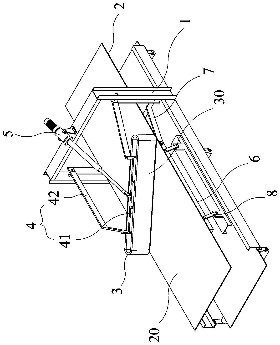
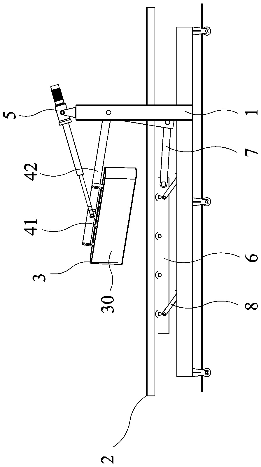
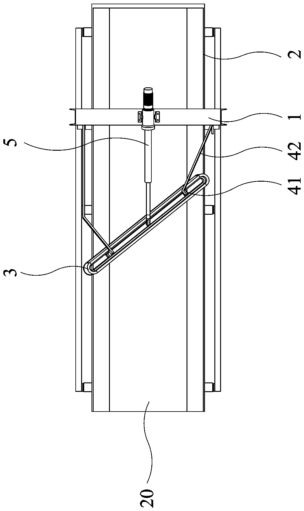
[0026] refer to Figure 1 to Figure 8 As shown, the present invention is a discharge structure of a belt conveyor, including a frame 1, a conveyor belt 2, a discharge belt 3 and a mounting bracket 4. Above-mentioned conveyor belt 2 is installed on the frame 1. The above-mentioned mounting bracket 4 includes a mounting part 41 and a connecting rod group 42. The discharge belt 3 is sleeved on the periphery of the mounting part 41, and the lower end of the discharge belt 3 is movably matched with the upper surface of the conveyor belt 2. The upper surface of the mounting part 41 is in contact with the One end of the connecting rod group 42 is connected, and the other end of the connecting rod group 42 is installed on the frame 1 . The inner ring of the above-mentioned unloading belt 3 is formed with a plurality ...


PUM


Abstract

The invention discloses an unloading structure of a belt conveyor. The unloading structure comprises a rack, a conveying belt, an unloading belt and a mounting bracket; the conveying belt is arrangedon the rack; the mounting bracket comprises a mounting part and a connecting rod group; the unloading belt is movably arranged on the periphery of the mounting part in a sleeving manner, the lower endof the unloading belt is matched with the upper surface of the conveying belt, the mounting part is connected with one end of the connecting rod group, and the other end of the connecting rod group is arranged on the rack; and the unloading plane of the unloading belt is inclined to the conveying plane of the conveying belt, and the unloading direction of the unloading belt is inclined to the conveying direction of the conveying belt. The unloading plane and the unloading direction of the unloading belt are respectively inclined to the conveying plane and the conveying direction of the conveying belt, so that stress decomposition of the unloading belt is achieved to generate the line speed, the impact force of materials is decomposed, so that flying dust and spillage are reduced, the rigid friction between the unloading belt and the conveying belt is avoided, the abrasion is reduced, and the service life is prolonged; and the moving speed of the materials in the unloading direction isensured, and the unloading efficiency is improved.

Description

technical field [0001] The invention relates to the field of transmission machinery, in particular to a discharge structure of a belt conveyor. Background technique [0002] Plow unloaders are widely used in belt conveyor systems. The plow unloader adopts the coulter and the belt to achieve rigid pressing contact, and changes the moving direction of the material through the coulter guide, so that the material is plowed into the hopper. Since the coulter is fixed, but the belt and the material are moving, this working mechanism will lead to the following problems: 1. The flow of material has a great impact on the coulter, and the working part of the plow unloader is fully open 2. The coulters wear out quickly and are easy to scratch the belt, which affects the service life; 3. Bring extra load to the rotation of the belt and increase energy consumption; 4. Due to the flow of materials Blocked by coulters, the loss of kinetic energy is relatively large, and when the material...

Claims


Application Information

Patent Timeline
Patent Type & Authority Applications(China)
IPC IPC(8): B65G47/34B65G39/12
CPCB65G39/12B65G47/34
Inventor 肖衍滋彭清围卢维泉卢禄华李涪银卢晓敏郑银钻
Owner 厦门三烨清洁科技股份有限公司
Why Eureka
Try Eureka