Winding device used for flexible LED filament production

A technology of LED filament and winding device, which is applied in lighting devices, transportation and packaging, and conveying filamentous materials, etc. It can solve the problems of uneven winding and dust cleaning on the surface of the filament, etc.

Inactive Publication Date: 2019-09-06
贵州联尚科技有限公司
View PDF5 Cites 7 Cited by
  • Summary
  • Abstract
  • Description
  • Claims
  • Application Information

AI Technical Summary

Problems solved by technology

[0003] In the process of production and processing of flexible LED filament, the finished product needs to be wound. During the winding process of the existing winding device, the winding is not uniform enough, and the dust on the surface of the filament cannot be cleaned.

Method used


Image

  • Winding device used for flexible LED filament production
  • Winding device used for flexible LED filament production
  • Winding device used for flexible LED filament production

Examples


Embodiment 1

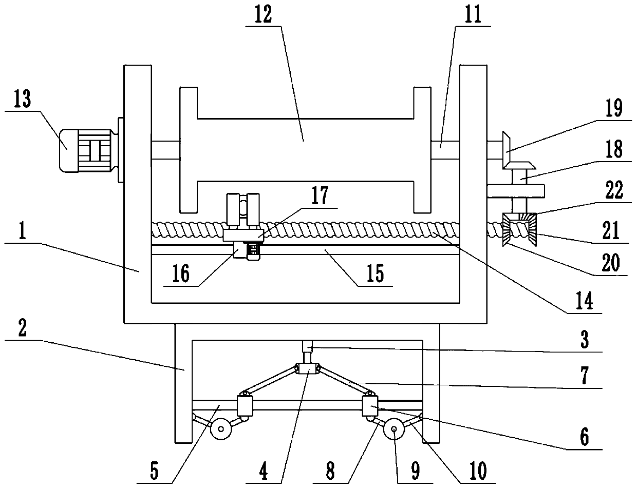
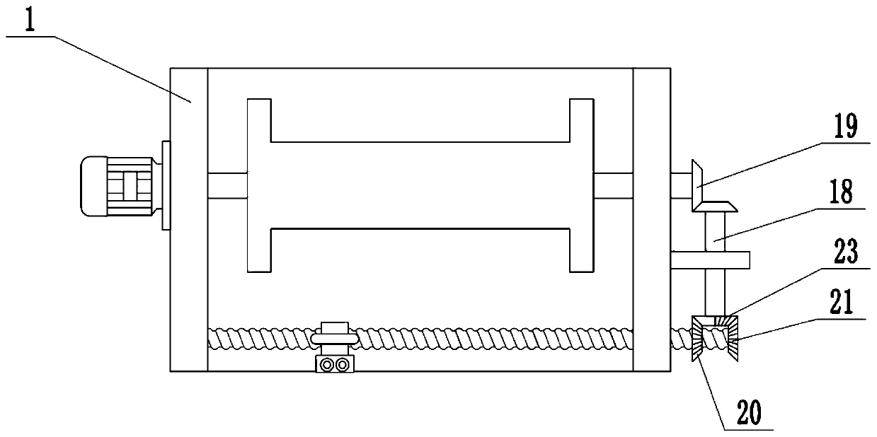
[0021] see Figure 1-4 , in an embodiment of the present invention, a winding device for the production of flexible LED filaments, including a fixed frame 1, a winding roller 12 and a winding motor 13, a support frame 2 is installed on the lower surface of the fixed frame 1, and the fixed frame 1 The drive shaft 11 is installed inside, and the left and right ends of the drive shaft 11 are respectively connected to the side wall of the fixed frame 1. The middle part of the drive shaft 11 is provided with a winding roller 12 for winding the flexible LED filament. The fixed frame 1 The outer wall of the outer wall is fixedly connected with a winding motor 13, and the shaft extension end of the winding motor 13 is connected with the winding roller 12, and the inside of the fixed frame 1 is also equipped with a screw mandrel 14, and the left and right ends of the screw mandrel 14 are connected with the fixed frame respectively. The side wall of 1 is rotationally connected, and the ...

Embodiment 2

[0023] On the basis of Embodiment 1, a moving mechanism is installed inside the support frame 2, and the moving mechanism includes a telescopic mechanism 3, a lifting block 4, a sliding rod 5, a movable block 6, a first connecting rod 7, a second connecting rod 8, a rolling Axis 9 and the third connecting rod 10, telescopic mechanism 3 are fixedly connected on the top of support frame 2, telescopic mechanism 3 is an electrohydraulic telescopic cylinder, and the lower end of telescopic mechanism 3 is fixedly connected with lifting block 4, and the left and right sides of lifting block 4 are all A first connecting rod 7 is hinged, and the lower end of the first connecting rod 7 is hinged with a movable block 6. A sliding rod 5 is arranged below the lifting block 4, and the left and right ends of the sliding rod 5 are fixedly connected with the side walls of the support frame 2 respectively. Slide bar 5 runs through movable block 6, and movable block 6 is slidingly connected with ...

Embodiment 1、 Embodiment 2

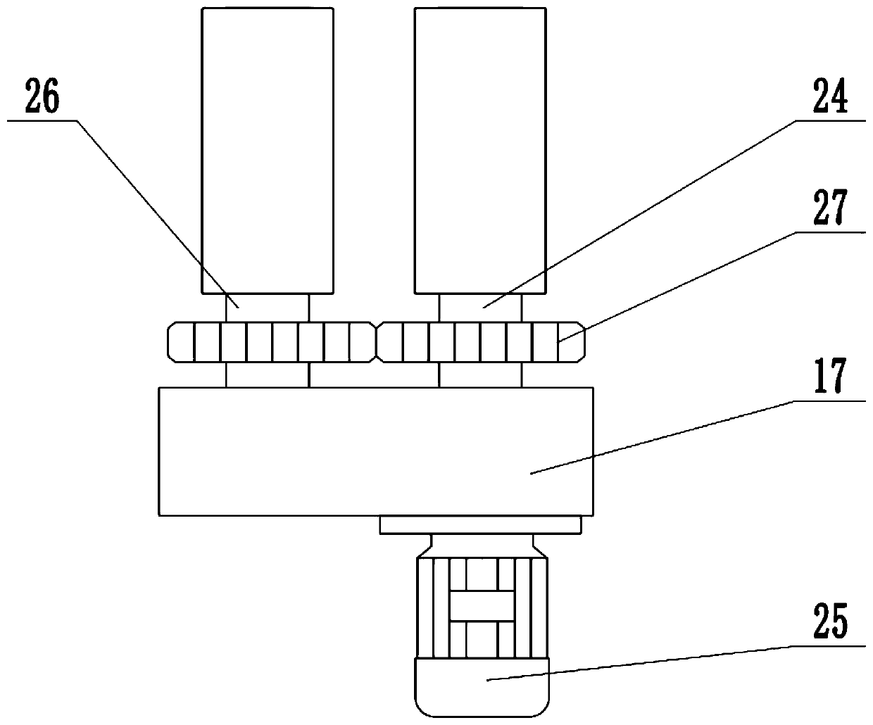
[0024] Combining Embodiment 1 and Embodiment 2, the working principle of the present invention is: the flexible LED filament to be wound passes between the active cleaning roller 24 and the driven cleaning roller 25, and is wound on the winding roller 12 through the guide ring 23 On, start the winding motor 13, drive the winding roller 12 to rotate, make the filament wind on the winding roller 12, when the driving shaft 11 rotates, drive the transmission shaft 18 to rotate through the bevel gear set 19, when the half bevel gear 22 and the left bevel When the gear 20 meshes, it drives the screw mandrel 14 to rotate. When the half bevel gear 22 separates from the left bevel gear 20 and meshes with the right bevel gear 21, it drives the screw mandrel 14 to reverse, and so on, so that the screw mandrel 14 is driven to rotate forward and backward, thereby Drive the slider 16 to move left and right, so that the filament is evenly wound on the winding roller 12, and at the same time s...


PUM


Abstract

The invention relates to the field of LED lamp production equipment, in particular to a winding device used for flexible LED filament production. The winding device comprises a fixing frame, a windingroller and a winding motor; a supporting frame is arranged on the lower surface of the fixing frame, a driving shaft is arranged in the fixing frame, the winding roller is arranged in the middle of the driving shaft in a sleeve mode,and the winding motor is fixedly connected to the outer side wall of the fixing frame; and a screw rod is further installed inside the fixing frame, a transmission shaft is arranged on the outer side wall of the fixing frame, a sliding block is arranged in the middle of the screw rod in a sleeve mode, a guide ring is fixedly connected to the upper surface of the sliding block, the side wall of the sliding block is fixedly connected to a fixing plate, a cleaning device is arranged on the fixing plate, and a moving mechanism is arranged inside the supporting frame. When winding operation is carried out by the winding device, a filament is wound around the winding roller, and meanwhile, the sliding block is driven to move left and right, so that the filamentis uniformly wound around the winding roller; and dust on the surface of the flexible LED filament is cleaned by utilizing a driving cleaning roller and a driven cleaning roller.

Description

technical field [0001] The invention relates to the field of LED lamp production equipment, more specifically, a winding device for flexible LED filament production. Background technique [0002] The substrate material of the flexible filament is made of extremely flexible polymer materials. The production process of flip-chip LED lamp beads has very high requirements on the heat resistance, light transmission and deformation resistance of the substrate. Medison tried more than a dozen materials, and finally found an ideal polymer material that could be used as a substrate. Printed circuits are made on polymer substrates, and flip-chip lamp beads are directly bound to the circuits to form HVLEDs in series. It is no longer necessary to use gold wire welding, the flexible LED filament can be bent at any angle to shape the filament, and the inside of the filament will not break, and the lamp will not die during use, which greatly improves the service life of the filament. The...

Claims


Application Information

Patent Timeline
Patent Type & Authority Applications(China)
IPC IPC(8): B65H54/28B65H54/70F21K9/90F21Y115/10
CPCB65H54/2818B65H54/702B65H2701/3915F21K9/90F21Y2115/10
Inventor 戴朋
Owner 贵州联尚科技有限公司
Why Eureka
Try Eureka