
Cutterhead expanding excavation method using special-shaped cutter

A cutter head and cutting tool technology, which is applied in mining equipment, earthwork drilling, tunnels, etc., can solve the problems of reduced tool life, many contact surfaces, and unavailable tool bodies, etc., to prolong the service life and reduce secondary wear.

Active Publication Date: 2019-09-06
CHINA RAILWAY TUNNEL GROUP CO LTD +2
View PDF7 Cites 0 Cited by
  • Summary
  • Abstract
  • Description
  • Claims
  • Application Information

AI Technical Summary

Problems solved by technology

This invention can be realized outside the tunnel, but during the excavation process of the TBM, there is no working space and hoisting equipment in the tunnel, and the side blocks of the cutter head are heavy (the weight of the side blocks of the cutter head with a diameter of 9m is as high as 40t), so it cannot be realized
Chinese patent number: CN201310689220.5, the patent title is "Height Adjustment Method of Hob Based on Spacers and Positioning Blocks", the inventors Huo Junzhou, Cai Bao, etc. disclosed a hob height adjustment method based on spacers and positioning blocks The method can realize the digging of the cutter head. This method has low structural rigidity, many contact surfaces, and poor practicability; Chinese patent number: CN201621061368. Zhang Shizhan and others disclosed a retractable side hob cutter box, through the relative movement of the inner and outer cutter boxes, combined with the increase in the height of the C-shaped block, the cutter head can be expanded and excavated
The methods adopted in patent CN201310689220.5 and patent CN201621061368.X both make the entire side cutter body move outside the excavation range of the cutter head, the cutter body cannot be protected by the cutter head, and the tool life drops sharply; Moving outside requires manual removal of the rock mass around the cutter head, but the TBM cutter head has a small opening range and the inner space of the cutter head is small, so manual work is difficult

Method used


Image

  • Cutterhead expanding excavation method using special-shaped cutter
  • Cutterhead expanding excavation method using special-shaped cutter
  • Cutterhead expanding excavation method using special-shaped cutter

Examples


Embodiment 1

[0029] Embodiment 1: A kind of cutterhead enlarging method that adopts special-shaped cutter, see Figure 1-Figure 4 , including the following steps:

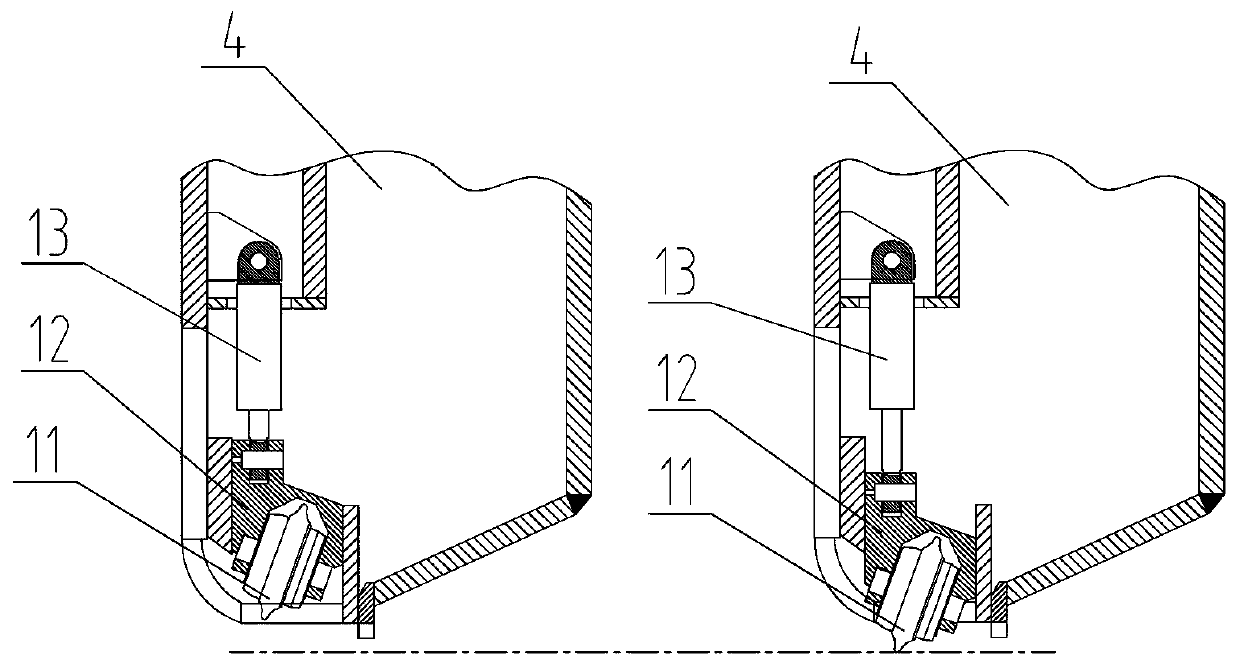
[0030] (1) At least one surrounding rock excavation hob 1 is arranged at the peripheral edge of the rock tunnel boring machine cutter head 4; the surrounding rock excavation hob 1 includes a hob cutter body 11, a movable knife seat 12 and a hydraulic cylinder 13. The hob cutter body 11 is fixed on the movable knife seat 12 by bolts, the bottom end of the hydraulic cylinder 13 is hinged with the cutter head 4, and the front end of the telescopic rod of the hydraulic cylinder 13 is hinged with the movable knife seat 12 .

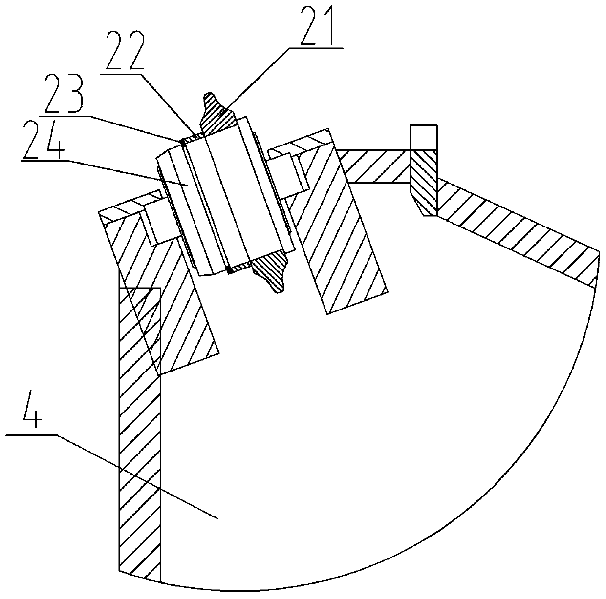
[0031] (2) A side edge hob 2 is provided at the peripheral edge of the cutter head 4, and the side edge hob 2 includes a knife ring 21, a sleeve 22, a retaining ring 23 and a side edge cutter body 24. The blade cutter body 24 is installed near the outermost edge side of the cutter head 4, and the sleeve 22 tu...


PUM


Abstract

The invention discloses a cutterhead expanding excavation method using a special-shaped cutter. Cutterhead expanding excavation is realized by arranging a surrounding rock chiseling hob, an eccentricblade hob, and a heightening scraper around a rock tunnel boring machine cutterhead; when the cutterhead needs to excavate, that is, when the diameter of a cross-section circle is increased, oil is supplied to a hydraulic cylinder, the surrounding rock chiseling hob slowly extends out of the cutterhead and breaks the surrounding rock with rotation of the cutterhead; manual cutting of the rock massaround the cutterhead in a small cutterhead space is not needed, and manual work can be replaced; then TBM continuous expanding excavation is realized by arranging the eccentric blade hob at the edgeof the circumferential of the cutterhead; and the cutterhead expanding excavation method using the special-shaped cutter can be used for TBM coping with construction of high ground stress soft rock convergence formation.

Description

technical field [0001] The invention relates to the technical field of rock tunnel excavation equipment, in particular to a method for expanding excavation with a cutter head using special-shaped cutters. Background technique [0002] Rock tunnel boring machine (TBM) is a special equipment for mountain tunnel construction, widely used in railway, engineering, subway, water conservancy, coal mine and other tunnel projects. When TBM is excavating in high ground stress soft rock convergent stratum, the cutterhead needs to have the function of expanding the excavation diameter. By increasing the excavation diameter, sufficient surrounding rock deformation is reserved. On the one hand, it can ensure that the tunnel can still meet the design clearance after the surrounding rock converges. On the other hand, it can also prevent the TBM shield from being stuck. Therefore, cutter head expansion is very important to improve the working performance of TBM. [0003] The design of TBM ...

Claims


Application Information

Patent Timeline
Patent Type & Authority Applications(China)
IPC IPC(8): E21D9/08
CPCE21D9/0874
Inventor 杨延栋陈馈洪开荣周建军李凤远张兵宋法亮韩伟锋刘俊成秦银平李宏波赵海雷王利明王唤龙卢松
Owner CHINA RAILWAY TUNNEL GROUP CO LTD
Learn More