Supercharge Your Innovation With Domain-Expert AI Agents!

Floating positioning pin and positioning method

A floating positioning and positioning pin technology, applied in the field of positioning pins, can solve the problems of complex positioning pin design and processing, easy to fall off and lose limit screws, and affect the use of fixtures, etc., to achieve simple structure, stable and reliable limit, convenient disassembly and The effect of replacement

Pending Publication Date: 2019-09-06
XIAN FASHITE AUTOMOBILE TRANSMISSION CO LTD
View PDF0 Cites 1 Cited by
  • Summary
  • Abstract
  • Description
  • Claims
  • Application Information

AI Technical Summary

Problems solved by technology

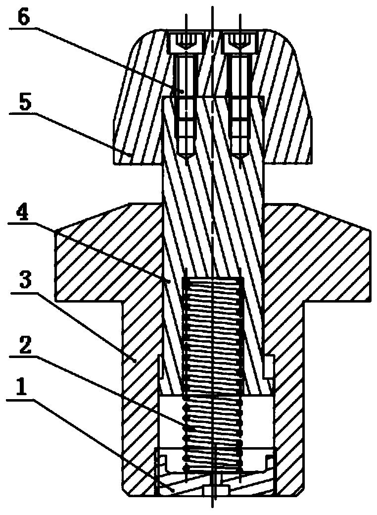
[0003] The existing floating locating pin mechanism is mainly composed of cylindrical taper pins, rhombic taper pins, locating pin seats, springs and limit screws. The locating pin is usually designed as a whole with the locating end and the sliding end, and a keyway is processed on the locating pin. , by using the limit screw to realize the angular limit and travel limit of the positioning pin, the design and processing of the positioning pin are more complicated, the production cost is high, and the limit screw is easy to fall off and lose, which affects the use of the fixture

Method used


Image

  • Floating positioning pin and positioning method
  • Floating positioning pin and positioning method
  • Floating positioning pin and positioning method

Examples


Embodiment Construction

[0043] In order to enable those skilled in the art to better understand the solutions of the present invention, the following will clearly and completely describe the technical solutions in the embodiments of the present invention in conjunction with the drawings in the embodiments of the present invention. Obviously, the described embodiments are only It is an embodiment of a part of the present invention, but not all embodiments. Based on the embodiments of the present invention, all other embodiments obtained by persons of ordinary skill in the art without making creative efforts shall fall within the protection scope of the present invention.

[0044] It should be noted that the terms "first" and "second" in the description and claims of the present invention and the above drawings are used to distinguish similar objects, but not necessarily used to describe a specific sequence or sequence. It is to be understood that the data so used are interchangeable under appropriate ...


PUM


Abstract

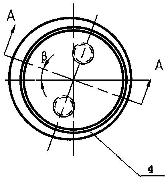
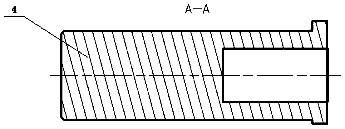
The invention discloses a floating positioning pin and a positioning method. The floating positioning pin comprises a positioning pin body, a spring, a pin base and a plugging piece. The first end ofthe positioning pin body is used for positioning a workpiece, the second end of the positioning pin body extends into a pin base hole formed in the pin base, and the tail end of the positioning pin body is provided with an annular protrusion. One end of the spring is connected with the end face of the second end of the positioning pin body, the other end of the spring is connected with the plugging piece, and the plugging piece is connected with the pin base hole. The pin base hole comprises a first through hole and a second through hole which communicates with each other, and the diameter ofthe first through hole is smaller than that of the second through hole. The second end of the positioning pin body can axially move in the pin base hole, the annular protrusion is located in the second through hole, and the diameter of the limiting protrusion is larger than that of the first through hole. The second end of the positioning pin body and the pin base hole are of an eccentric structure, and the second end of the positioning pin body and the pin base hole are identical in eccentric amount and eccentric vector direction. A sliding rod is designed into a stepped shaft type to achieveaxial stroke limiting. An eccentric hole is formed in the pin base, and an eccentric shaft is arranged on the sliding rod, so that axial rotation of the sliding rod is limited, and angular requirements of the positioning pin are met.

Description

technical field [0001] The invention belongs to the field of positioning pins and relates to a floating positioning pin and a positioning method. Background technique [0002] The function of the positioning pin is to limit the free movement of the item. The floating positioning pin mechanism is very common in blank processing, following the principle of "two pins on one side", using the precast hole of the blank to complete the positioning processing of the part. [0003] The existing floating locating pin mechanism is mainly composed of cylindrical taper pins, rhombic taper pins, locating pin seats, springs and limit screws. The locating pin is usually designed as a whole with the locating end and the sliding end, and a keyway is processed on the locating pin. , By using limit screws to realize the angular limit and stroke limit of the positioning pin, the design and processing of the positioning pin are more complicated, the production cost is high, and the limit screw i...

Claims


Application Information

Patent Timeline
IPC IPC(8): F16B19/02B23Q3/00
CPCF16B19/02B23Q3/00
Inventor 王卫波
Owner XIAN FASHITE AUTOMOBILE TRANSMISSION CO LTD
Features
  • R&D
  • Intellectual Property
  • Life Sciences
  • Materials
  • Tech Scout
  • Unparalleled Data Quality
  • Higher Quality Content
  • 60% Fewer Hallucinations
Learn More