Levelness measuring device for high-potential component of electrical device and method thereof
A technology for level measurement and electrical equipment, applied in the direction of measuring devices, measuring inclination, surveying and navigation, etc., to achieve the effects of reasonable design, high sensitivity, improved accuracy and real-time performance
- Summary
- Abstract
- Description
- Claims
- Application Information
AI Technical Summary
Problems solved by technology
Method used
Image

Examples
Embodiment Construction
[0027] Embodiments of the present invention will be described in further detail below in conjunction with the accompanying drawings.
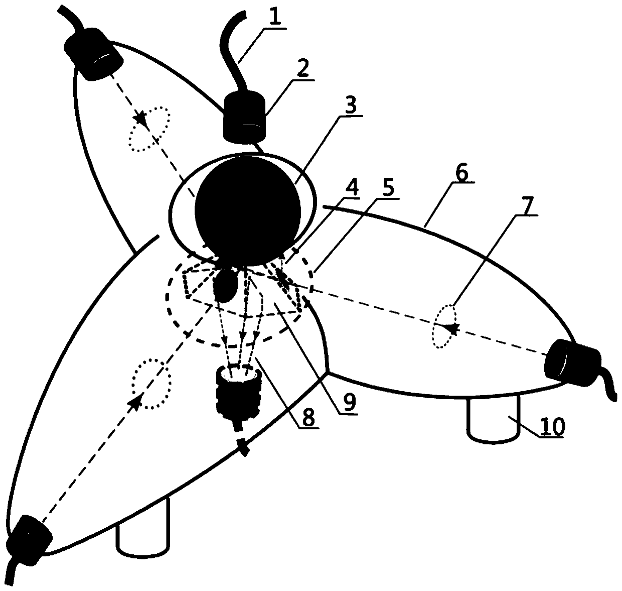
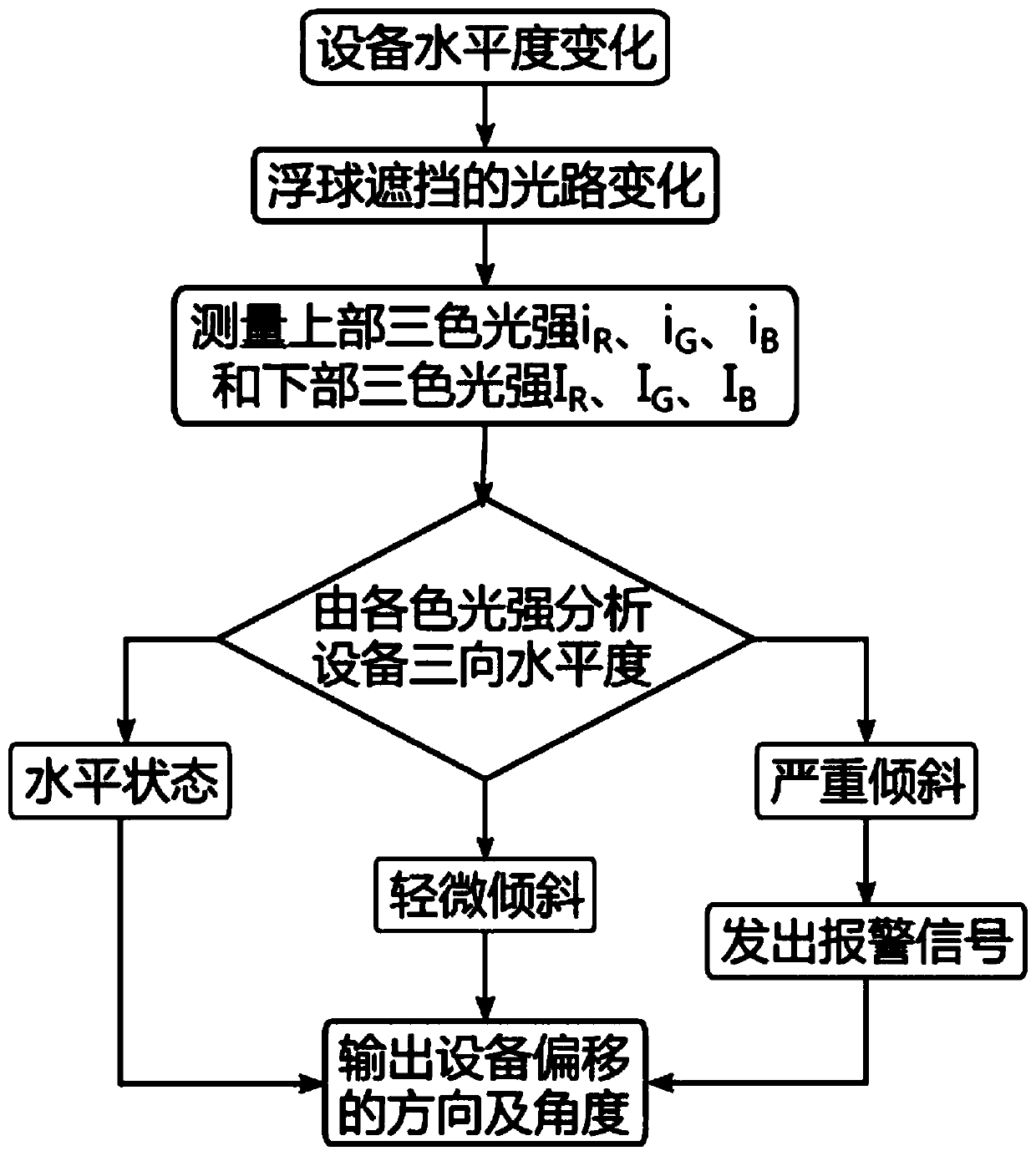
[0028] The design concept of the present invention is: the present invention converts the levelness in different directions in a high potential environment into optical signals with different color differences, and uses mixed light to represent the levelness after color light synthesis, and transmits it to the low potential end by optical fiber, through the light color- The levelness converter restores the mixed light to the levelness in different directions to realize levelness measurement. The measuring device for realizing the above method is mainly composed of a levelness-light color sensor and a light color-levelness converter. The optical fiber, lens, floating ball, etc. that make up the levelness-light color sensor are all non-metallic insulating materials, and the electric field and magnetic field interference in the high potential envi...
PUM
 Abstract
Description
Claims
Application Information