Alternating parallel nine-speed transformer on-load voltage regulation circuit capable of polarity conversion

A voltage regulation circuit and polarity conversion technology, which can be used in conversion equipment that can be converted to DC without intermediate conversion, output power conversion devices, and AC power input is converted into AC power output. It can solve problems such as complex switch structures , to achieve the effect of reducing the number of opening and closing, small voltage fluctuation and long service life

Pending Publication Date: 2019-09-06
ZHEJIANG BOTHWELL ELECTRIC
View PDF2 Cites 5 Cited by
  • Summary
  • Abstract
  • Description
  • Claims
  • Application Information

AI Technical Summary

Problems solved by technology

The upper limit of its on-off times determines the service life of the voltage regulating switch designed according to this circuit." This defect remains unchanged.
And as the number of switch gears increases, the number of transition circuit selection switches also increases, and the switch structure tends to be complicated

Method used


Image

  • Alternating parallel nine-speed transformer on-load voltage regulation circuit capable of polarity conversion
  • Alternating parallel nine-speed transformer on-load voltage regulation circuit capable of polarity conversion

Examples


Embodiment Construction

[0039] The structural characteristics and working principle of the nine-speed transformer voltage regulating circuit with polarity conversion described in the present invention will be further described below in conjunction with the accompanying drawings.

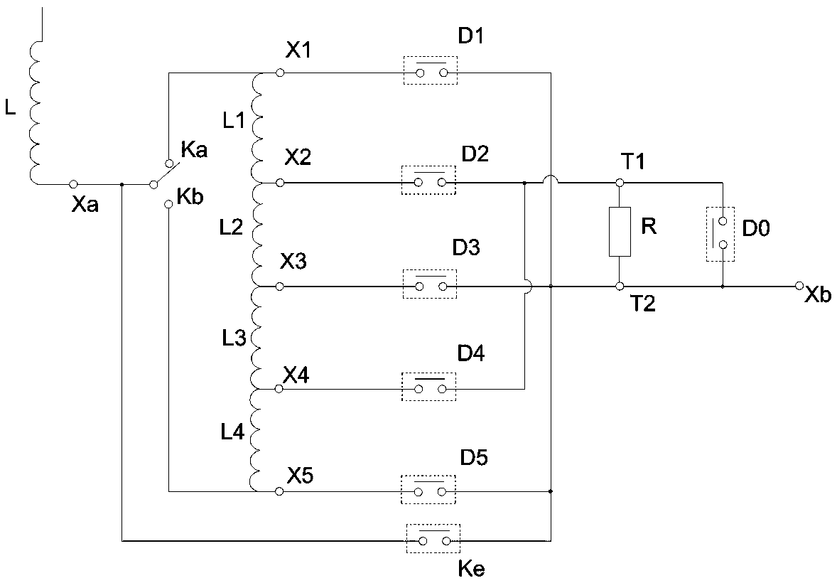
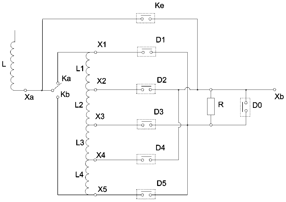
[0040] see figure 1 Shown is a schematic diagram of a nine-speed transformer voltage regulating circuit under the technical solution of the present invention. The circuit is composed of a main winding, a voltage regulating winding, a rated voltage branch, a transition switching unit, and five voltage regulating branches.

[0041] The transition switching unit includes a first input terminal T1, a second input terminal T2, an output terminal Xb, and a vacuum interrupter D0 connected in series between the first input terminal T1 and the output terminal Xb in parallel with a transition resistor R.

[0042] The first voltage regulating coil L1, the second voltage regulating coil L2, the third voltage regulating coil L3, and the...


PUM


Abstract

The invention relates to the field of distribution transformers and provides an alternating parallel nine-speed transformer on-load voltage regulation circuit capable of polarity conversion, and the circuit comprises a main winding, a polarity conversion switch, a voltage regulating winding, a transition switching unit, a rated voltage branch and five voltage regulating branches. The circuit provided by the invention sets a polarity conversion switch between the main winding and the voltage regulating winding, and realizes positive and negative pressure regulation by adjusting the independentcontact connecting end of the polarity conversion switch. One ends of the respective voltage regulating branches are respectively connected to two end taps and each of the intermediate taps of the voltage regulating winding; the other ends are adjacently staggered and connected in parallel in two groups and respectively connected with two input ends of the transition switching unit; the input endof the rated voltage branch is connected to the taps of the output end of the main winding, and the output of the rated voltage branch is connected to the output end of the voltage regulating circuit.The circuit has the beneficial effects of reducing the on-off frequency of the on-off switch, increasing the service life of the corresponding pressure regulating switch, and during the voltage-regulating process, varying the transition voltage with the pressure regulating gear position with no shifting pressure regulation required.

Description

technical field [0001] The invention relates to the field of distribution and transformation transformers, in particular to an on-load voltage regulation circuit of a transformer. Background technique [0002] In the patent with the application number 201610121960 and the title: "A Permanent Magnet Vacuum On-Load Voltage Regulator, Transformer and On-Load Voltage Regulation Method", it provides a method of using two vacuum interrupters to form the main circuit and the transition circuit respectively. Structural on-load voltage regulation method. The key points of this technical solution are: during normal operation, the vacuum interrupter of the main circuit is connected, the main circuit is in the connected state, the vacuum interrupter of the transition circuit is disconnected, the transition circuit is in the disconnected state, The pressure winding determines the external voltage supply gear of the circuit. When the gear is switched, the transition circuit vacuum inter...

Claims


Application Information

Patent Timeline
Patent Type & Authority Applications(China)
IPC IPC(8): H02P13/06
CPCH02P13/06
Inventor 吴正文姜方军
Owner ZHEJIANG BOTHWELL ELECTRIC
Why Eureka
Try Eureka