
Compression device for straw baler

Active Publication Date: 2019-09-10
ANHUI SCI & TECH UNIV +1
View PDF7 Cites 3 Cited by
  • Summary
  • Abstract
  • Description
  • Claims
  • Application Information

AI Technical Summary

Problems solved by technology

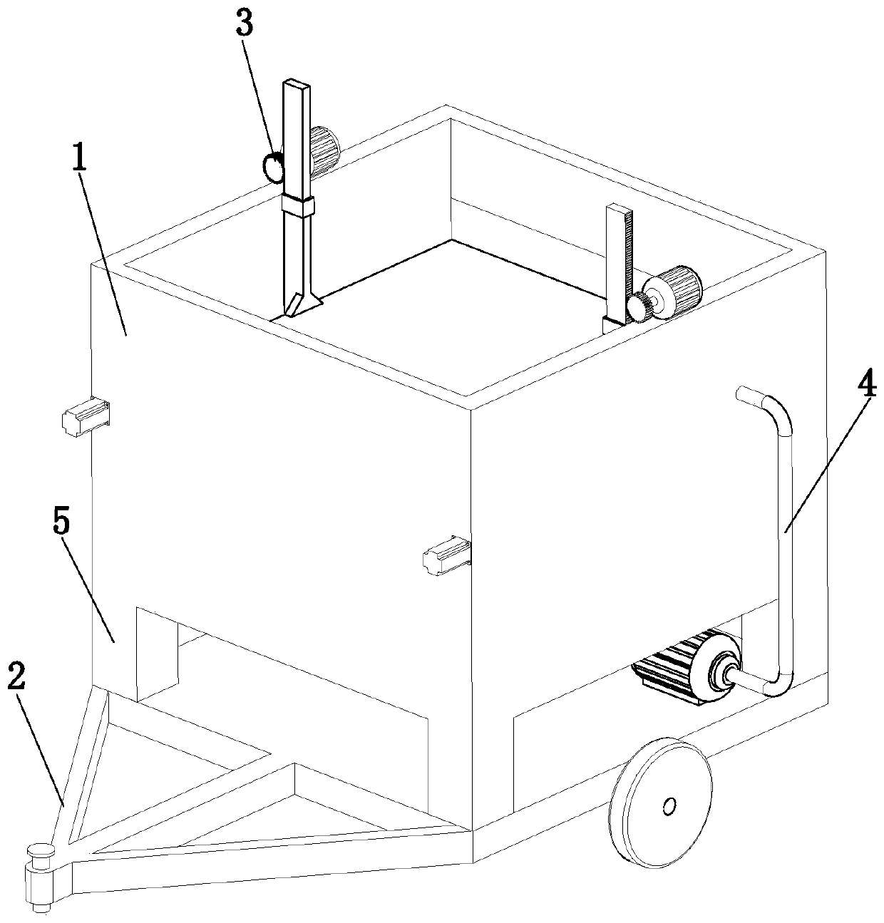
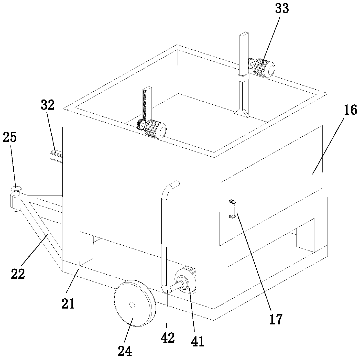
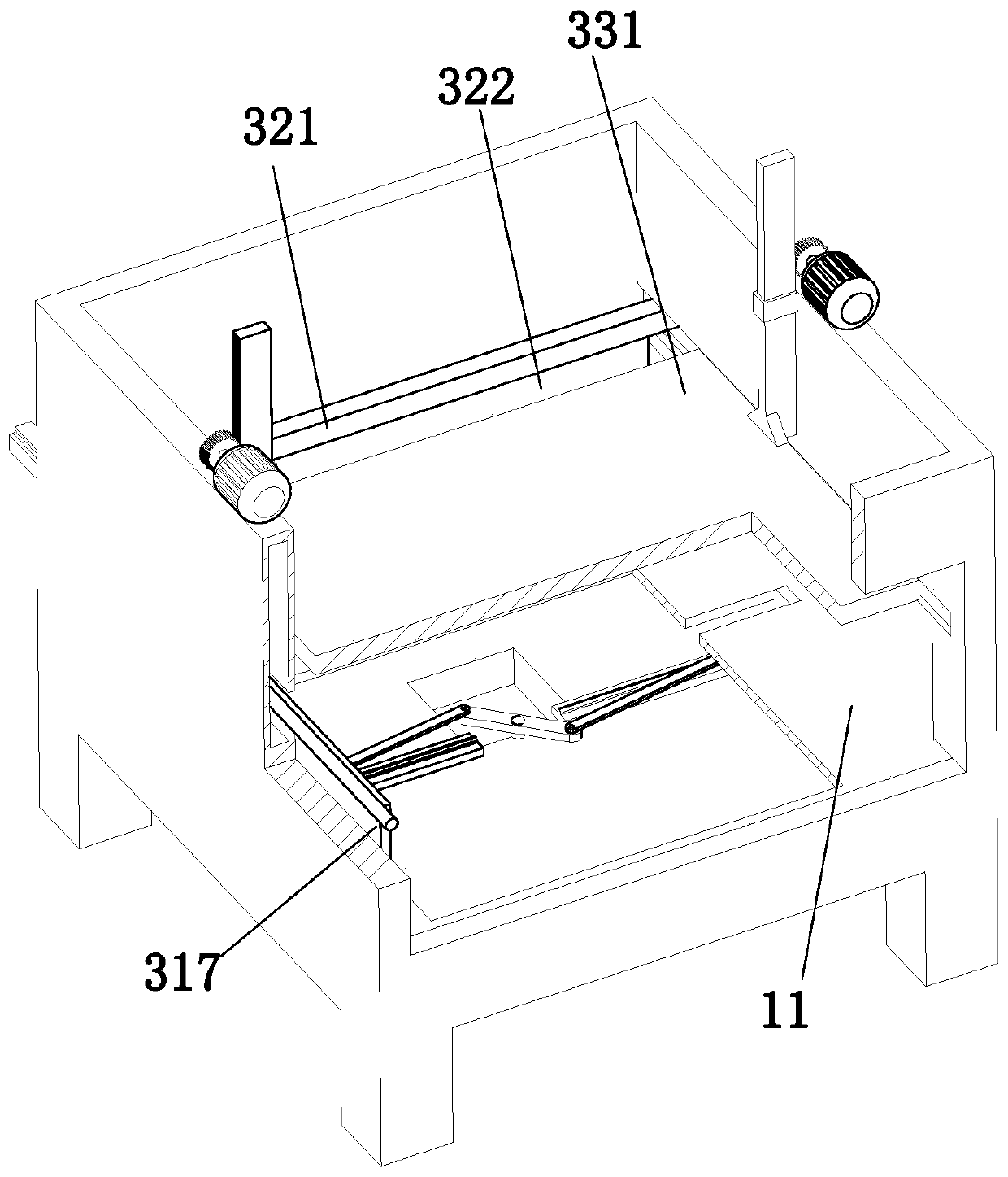
[0005] The technical problem to be solved by the present invention is to provide a straw baler compression device to solve the technical problems in the prior art that the straw can only be compressed in one direction and the box cannot be cleaned, resulting in dust in the box

Method used


Image

  • Compression device for straw baler
  • Compression device for straw baler
  • Compression device for straw baler

Examples


Embodiment Construction

[0030] In order to make the object, technical solution and advantages of the present invention clearer, the present invention will be further described in detail below in conjunction with the accompanying drawings and embodiments. It should be understood that the specific embodiments described here are only used to explain the present invention, not to limit the present invention.

[0031] In describing the present invention, it should be understood that the terms "longitudinal", "transverse", "upper", "lower", "front", "rear", "left", "right", "vertical", The orientations or positional relationships indicated by "horizontal", "top", "bottom", "inner", "outer", etc. are based on the orientations or positional relationships shown in the drawings, and are only for the convenience of describing the present invention, rather than indicating or It should not be construed as limiting the invention by implying that a referenced device or element must have a particular orientation, be...


PUM


Abstract

The invention discloses a compression device for a straw baler and belongs to the technical field of compression devices for balers. The compression device comprises a compression box, a traveling component, a compression component, and a cleaning component; one end of the cleaning component is arranged at the top of the traveling component and positioned below a mounting frame; the other end of the cleaning component is extended into the compression box; a partition horizontally arranged is arranged on the compression box and divides the compression box into a first receiving chamber and a second receiving chamber; the compression component comprises a first compression part, a second compression part and third compression parts; the first compression part is arranged at the bottom of thecompression box and positioned in the first receiving chamber; the second compression part is arranged on the compression box and in sliding fit with the compression box; the third compression partsare arranged at the top of the compression box and are in sliding fit with the compression box. The compression device can provide comprehensive compression for straws through the first compression part, the second compression part and the third compression parts; the straws are compressed to smaller size, so that the straws can be transported and stored later easily.

Description

technical field [0001] The invention relates to the technical field of a baler compression device, in particular to a straw baler compression device. Background technique [0002] Reasonable utilization of crop straw must first be harvested with a straw baler. At present, square balers are mostly used to harvest straw, and most of the compression chambers use crank slider compression mechanisms. This mechanism has the advantages of simple structure and low manufacturing cost. The disadvantage is that the compression force of the baler on the straw is limited by the power of the machine, and the compression force directly affects the size and density of the straw bales. It is necessary to improve production efficiency and obtain large-sized, high-density straw bales. [0003] For example, the patent with publication number CN108076858A relates to a straw baler compression device, including a bracket, two fixed blocks are arranged on the rear side of the lower surface of the b...

Claims


Application Information

Patent Timeline
Patent Type & Authority Applications(China)
IPC IPC(8): A01F15/08A01B71/08
CPCA01B71/08A01F15/08
Inventor 郑凤菊鲍官培许自立张春雨张静波路超曹强
Owner ANHUI SCI & TECH UNIV
Learn More