Axial feeding device and charging docking device

A technology of axial feed and motor seat, which is applied in the field of mechanical arms, can solve the problems of inability to adjust the operating direction or operating position, and achieve the effect of simple structure and low cost

Pending Publication Date: 2019-09-10
GUOCHUANG INNOVATION CENTER OF MOBILE ENERGY (JIANGSU) CO.,LTD.
View PDF7 Cites 5 Cited by
  • Summary
  • Abstract
  • Description
  • Claims
  • Application Information

AI Technical Summary

Problems solved by technology

[0009] The purpose of the present invention is to overcome the defect that the operating direction or operating position cannot be adjusted during the axial feeding process in the prior art, and to provide an axial feed operation that can perform axial feeding after adjusting the operating direction or operating position. Feeding device

Method used


Image

  • Axial feeding device and charging docking device
  • Axial feeding device and charging docking device
  • Axial feeding device and charging docking device

Examples


Embodiment 1

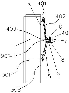
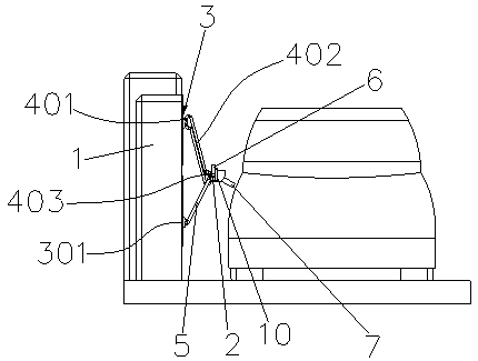
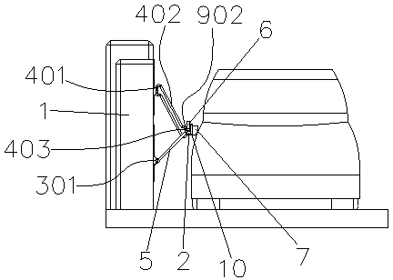
[0074] like Figure 1-Figure 6 The shown embodiment one of an axial feed device of the present invention includes a base 1 and an adjustment seat 2, and one side of the base 1 is provided with three linear drive devices 3, and each linear drive device 3 includes a linear As for the motion component, the moving trajectories of the three linear motion components are arranged in parallel and form a character shape; among the three linear motion components, the middle linear motion component is rotated and connected to a limit rod 401, and both ends of the limit rod 401 are hinged. Fork 402, movable rod 403 is hinged between two swing rods 402, limit rod 401, two swing rods 402 and movable rod 403 constitute a parallelogram mechanism, and the motion track line of the linear motion component in the middle is consistent with the parallelogram mechanism. The motion trajectory curves are all located on the same plane, the movable rod 403 is installed on the adjustment seat 2, and the ...

Embodiment 2

[0094] like Figure 16-Figure 17 Shown is the second embodiment of an axial feed device of the present invention. The difference between this embodiment and the first embodiment is that the linear drive device 3 is a rack and pinion transmission device, wherein, when the linear motion component is a rack 304, the side of the base 1 is provided with a first groove 12 and a second motor 13, the gear 302 is arranged in the first groove 12, and the output shaft of the second motor 13 passes through the side wall of the first groove 12 and Stretch in the slot, the gear 302 is installed on the output shaft of the second motor 13, the gear 302 and the rack 304 mesh with each other, and the two sides of the rack 304 are successively provided with a plurality of protrusions 303 along the length direction, and the first groove The groove walls on both sides of 12 are provided with strip-shaped grooves 1201 along the direction of the groove body, and each protrusion 303 is slidably conne...

Embodiment 3

[0097] like Figure 18-Figure 19The third embodiment of an axial feed device of the present invention is shown. The difference between this embodiment and the first embodiment is that the linear drive device 3 is another rack and pinion transmission device, wherein the linear motion assembly includes Gear 302, slide block 307 and second motor 13, rack 304 are installed on the side of base 1, and rack 304 two ends are provided with end plate 305, two end plates 305 are vertically fixed on the side of base 1, two Several guide rods 306 are vertically fixedly connected between each end plate 305, and the slider 307 is slidably connected to each guide rod 306. The second motor 13 is installed on the slider 307, and the gear 302 is installed on the output shaft of the second motor 13. , the gear 302 and the rack 304 mesh with each other. The second motor 13 drives the gear 302 to roll on the rack 304 , and then drives the slider 307 to slide on the track formed by the guide rods 3...


PUM


Abstract

The invention belongs to the technical field of mechanical arms, and particularly relates to an axial feeding device and a charging docking device; the axial feeding device comprises a base and an adjusting seat; one side of the base is provided with three linear driving devices, and each linear driving device comprises a linear motion assembly; the middle linear motion assembly is rotationally connected with a limiting rod; swing rods are hinged to two ends of the limiting rod, and a movable rod is hinged between the two swing rods; the limiting rod, the two swing rods and the movable rod form a parallelogram mechanism; the movable rod is installed on the adjusting seat; the linear motion assemblies on two sides are connected with connecting rods through universal ball joints, and the twoconnecting rods are connected to the adjusting seat through universal ball joints; a first motor is mounted on the adjusting seat, and an output shaft of the first motor is connected to the movable rod; the adjusting seat is used for installing operation tools. The device has the beneficial effects that the adjusting seat can rotate leftwards and rightwards to adjust the operation tool to a required operation direction, and/or the axial feeding operation is carried out after the operation position of the operation tool is adjusted.

Description

technical field [0001] The invention belongs to the technical field of mechanical arms, and in particular relates to an axial feeding device and a charging docking device. Background technique [0002] In many occasions, for some operating tools, axial feeding operation is required; but at present, there is no device with simple structure, low equipment cost and the ability to perform axial feeding operation after adjusting the operating direction or operating position. [0003] For example, when the drilling direction of the workpiece needs to be adjusted, it is also necessary to manually disassemble the drill gun or manually adjust the position of the drill gun, and then hand it over to the equipment for axial feeding operation. Another example, especially in the field of new energy technology, the charging gun needs to be fed axially to charge the docking electric vehicle, and the automatic charging equipment for electric vehicles needs to adjust the direction of the ch...

Claims


Application Information

Patent Timeline
Patent Type & Authority Applications(China)
IPC IPC(8): B60L53/16B60L53/35B60L53/60
CPCB60L53/16B60L53/35B60L53/60Y02T10/70Y02T90/14Y02T10/7072Y02T90/12
Inventor 曹伟胡强钱磊邵丹薇郑隽一张育铭李德胜
Owner GUOCHUANG INNOVATION CENTER OF MOBILE ENERGY (JIANGSU) CO.,LTD.
Why Eureka
Try Eureka