
Path tracking control method suitable for high-speed limiting working condition

A technology of path tracking and extreme working conditions, which is applied to control devices and other directions, and can solve problems such as path tracking failures

Inactive Publication Date: 2019-09-10
CHANGCHUN UNIV OF TECH
View PDF7 Cites 11 Cited by
  • Summary
  • Abstract
  • Description
  • Claims
  • Application Information

AI Technical Summary

Problems solved by technology

[0008] In order to solve the problem of path tracking failure caused by the inaccurate expression of tire force in the traditional path tracking control method when the automatic driving vehicle avoids collisions under high-speed limit conditions, the present invention provides a path tracking control method suitable for high-speed limit conditions

Method used


Image

  • Path tracking control method suitable for high-speed limiting working condition
  • Path tracking control method suitable for high-speed limiting working condition
  • Path tracking control method suitable for high-speed limiting working condition

Examples


Embodiment Construction

[0103] The present invention will be described in detail below in conjunction with the accompanying drawings and embodiments.

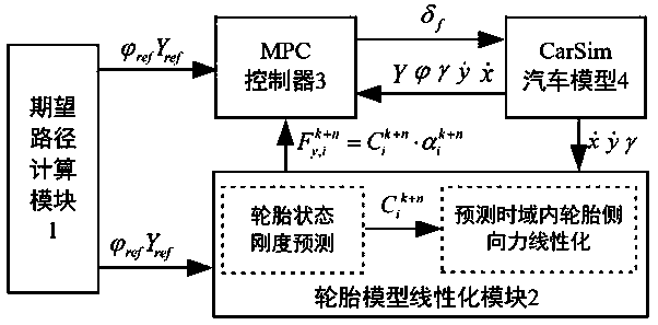
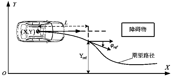
[0104] figure 1It is a system structural diagram of a path tracking control method suitable for high-speed extreme working conditions of the present invention. The system mainly includes a desired path calculation module 1, a tire model linearization module 2, an MPC controller 3 and a CarSim vehicle model 4; the desired path The calculation module 1 is used to calculate the expected lateral displacement and yaw angle of the vehicle; the tire model linearization module 2 is used to realize the linear approximation of the nonlinear tire force in the predicted time domain; the CarSim vehicle model 4 is used to output the actual state quantity of the vehicle, Including vehicle longitudinal velocity, lateral velocity, yaw angular velocity, yaw angle and lateral displacement; MPC controller 3 solves the front wheel angle of the vehicle according to the exp...


PUM


Abstract

A path tracking control method suitable for a high-speed limiting working condition is characterized in that the method comprises an expected path calculation module, a tire model linearization module, an MPC controller and a CarSim automobile model; the expected path calculation module is used for calculating an expected lateral displacement and a yaw angle of the automobile; the tire model linearization module is used for realizing linear approximation of nonlinear tire force in a prediction time domain; the CarSim automobile model is used for outputting the actual state quantity of the automobile, wherein the actual state quantity comprises a longitudinal speed, a lateral speed, a yaw velocity, the yaw angle and the lateral displacement of the automobile; and the MPC controller is usedfor solving a front wheel turning angle of the automobile according to the expected lateral displacement, the expected yaw angle and the actual state quantity of the automobile, inputting the front wheel turning angle to the CarSim automobile model, and controlling the automobile to realize path tracking control.

Description

[0001] Technical field: [0002] The invention relates to the field of vehicle path tracking control, and relates to a path tracking control method suitable for high-speed extreme working conditions. [0003] Background technique: [0004] With the increasing traffic congestion and road safety issues, self-driving cars have become the development trend of the automotive industry. Due to the complexity of the actual road environment and the strong nonlinearity of the car itself, the tracking control of autonomous vehicles faces great challenges. [0005] Scholars at home and abroad have made a lot of research results in the tracking control algorithm of automatic driving vehicles. The traditional control methods mainly include robust control, preview control and sliding mode control. But the above methods usually can only utilize the current environment information and the state of the car, and it is difficult to consider the constraints of the environment and the car. Therefo...

Claims


Application Information

Patent Timeline
IPC IPC(8): B60W30/165B60W50/00
CPCB60W30/165B60W50/0097B60W2050/0031
Inventor 李绍松王枫张邦成张袅娜卢晓晖于志新韩玲王国栋
Owner CHANGCHUN UNIV OF TECH
Learn More